Обзор
Новые серии частотных преобразователей SINAMICS G120 предназначены для обеспечения точного и эффективного управления скоростью/моментом двигателей AC.
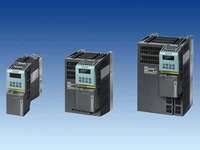
Существует большое количество приводных решений с разными версиями устройств (размеры корпуса FSA до FSF) в диапазоне выходной мощности от 0.37 кВт до 90 кВт.

Примеры SINAMICS G120, размеры корпуса FSA, FSB и FSC; каждый с силовым модулем, блоком управления и базовой панелью оператора

Примеры SINAMICS G120, размеры корпуса FSD, FSE и FSF; каждый с силовым модулем, блоком управления и базовой панелью оператора
Модульность
SINAMICS G120 – это модульная система преобразования, включающая в себя множество функциональных устройств. Двумя основными устройствами являются
- Блок управления (CU) и
- Силовой модуль (PM)
Блок управления управляет и контролирует силовой модуль и подключенный двигатель в разных режимах. Он поддерживает коммуникацию с локальным или центральным контроллером и с контрольной аппаратурой или входными/выходными клеммами для прямого управления.
Силовой модуль питает двигатель в диапазоне мощности от 0.37 кВт до 90 кВт. Силовой модуль управляется микропроцессором в блоке управления. Современная технология IGBT с напряжением двигателя с широтно-импульсной модуляцией и выбранная импульсная частота используются для достижения очень надежной и гибкой работы двигателя. Большой диапазон защитных функций обеспечивает высокий класс защиты двигателя.
Кроме того, имеется большое количество дополнительных компонентов, таких как:
- Базовая панель оператора (BOP) для базового программирования и копирования параметров привода
- Сетевой фильтр, классы A и B
- Сетевые дроссели
- Тормозные резисторы
- Выходные дроссели для длинных кабелей двигателя
Safety integrated
Диапазон SINAMICS G120 включает в себя преобразователи для задач с ориентацией на безопасность. Конструкция всех силовых модулей практически безотказная. Можно получить Safety Integrated Drive, объединив силовой модуль с соответствующим надежным блоком управления.
Надежные частотные преобразователи SINAMICS G120 обеспечивают четыре функции безопасности, сертифицированные в соответствие с EN 954-1 кат. 3 и IEC 61508 SIL 2:
- Безопасный останов 1 (SS1)
- Безопасно ограниченная скорость (SLS)
- Безопасное управление тормозом (SBC)
- Безопасное отключение момента (STO)
Новая концепция охлаждения и лакировка электронных модулей
Значительное увеличение срока службы или периода эксплуатации достигается благодаря новой системе охлаждения и лакировке электронных модулей. Эти свойства базируются на следующих принципах:
- Отвод всех потерь тепла через внешний радиатор
- Электронные модули не располагаются в воздуховодах
- Естественное охлаждение электронных компонентов
- Станлартное конвекционное охлаждение блока управления
- Весь охлаждающий воздух направляется через радиатор
Программа пуско-наладки привода STARTER
Программа пуско-наладки привода STARTER поддерживает пуско-наладку и техобслуживание преобразователей SINAMICS G120. Она обеспечивает руководство действиями оператора для упрощения и ускорения пуско-наладки вместе с обширными удобными для пользователя функциями для соответствующего приводного решения.
Область применения
SINAMICS G120 is ideal
- as a universal drive in all industrial and commercial applications
- in the automotive, textiles, printing, and chemical industries
- for end-to-end applications, e.g. in conveyor systems
Тех. данные
Особенности
- Modularity ensures flexibility for an advanced drive concept
- Module replacement when system is running (hot swapping)
- Pluggable terminals
- The modules can be easily replaced, which makes the system extremely service friendly.
- The safety functions make it easier to integrate drives into safety-oriented machines or plants
- Capable of communicating via PROFINET or PROFIBUS with PROFIdrive Profil 4.0
- Reduced number of interfaces
- Plant-wide engineering
- Easy to handle
- The innovative circuit design (bidirectional input rectifier with "pared-down" DC link) allows the kinetic energy of a load to be fed back into the supply system when Power Modules PM250 and PM260 are implemented. This feedback capability provides enormous potential for savings because generated energy no longer has to be converted into heat in a braking resistor
- Innovative SiC semiconductor technology ensures that when a PM260 Power Module is used, the inverter is more compact than a comparable standard inverter with an optional sine-wave filter for the same output
- A new cooling concept and paint finish for the electronic modules increase robustness and service life
- Simple unit replacement and quick copying of parameters using the optional Basic Operator Panel or the optional MMC memory card
- Low-noise motor operation resulting from high pulse frequency
- Compact, space-saving construction
- Software parameters for easy adaptation to 50 Hz or 60 Hz motors (IEC or NEMA motors)
- 2/3-wire control (static/pulsated signals) for universal control via digital inputs
- Engineering and commissioning with uniform engineering tools such as SIZER, STARTER, and Drive ES: ensure rapid engineering and easy commissioning – STARTER is integrated in STEP 7 with Drive ES Basic with all the advantages of central data storage and totally integrated communication
- Certified worldwide for compliance with CE, UL, cUL, c-tick, Safety Integrated to IEC 61508 SIL 2
Дизайн
The SINAMICS G120 inverter chassis units are modular frequency inverters for standard drives. Each SINAMICS G120 comprises two operative units – the Power Module and Control Unit. Each Control Unit can be combined with each Power Module.
Guide for module selection
The steps to be taken for the selection of a complete SINAMICS G120 frequency inverter should be as follows:
|
|
|
|
1st
|
Selection of the appropriate Control Unit (in dependence of the required style depth of communication, hardware and software)
|
|
2nd
|
Selection of the appropriate Power Module (in dependence of the necessary performance and technology)
|
|
3rd
|
Selection of the optional additional components. A large number of components for expanding the system is available, e. g. line-side power components, DC link components, load-side power components, and supplementary system components. Please note that not every component is required for every Power Module (example: Braking resistors are not necessary for PM250 and PM260 Power Modules!). You can find the exact indications in the technical data tables of the respective components.
|
Control Units
The following Control Units and an MMC memory card are available as accessories for SINAMICS G120 inverter chassis units:
CU240 Control Units
The Control Unit performs closed-loop control functions for the inverter. In addition to control functions, the Control Unit can also perform other tasks which can be adapted to the relevant application by parameterization. A number of Control Units are available in different versions:
- CU240E
- CU240S
- CU240S DP
- CU240S DP‑F
- CU240S PN
- CU240S PN-F
MMC memory card (not available for Control Unit CU240E)
The parameter settings for an inverter can be stored on the MMC memory card. When the plant is serviced, it is immediately ready for use again after, for example, replacement of the frequency inverter and transfer of the memory card data. The associated slot is located on top of the Control Unit.
Power Modules
The following Power Modules are available for SINAMICS G120 inverter chassis units:
PM240 Power Modules
PM240 Power Modules (0.37 kW to 90 kW) feature an integrated brake chopper and are designed for drives without energy recovery capability. Generator energy produced during braking is converted to heat via externally connected braking resistors.
PM250 Power Modules
PM250 Power Modules (7.5 kW to 132 kW) use an innovative circuit design which allows line-commutated energy recovery to the supply. This innovative circuit permits generator energy to be fed back into the supply system and therefore saves energy.
PM260 Power Modules
PM260 Power Modules (11 kW to 55 kW) also use an innovative circuit design which allows line-commutated energy recovery to the supply. This innovative circuit permits generator energy to be fed back into the supply system and, therefore, saves energy. The PM260 Power Modules also have an integrated sine-wave filter that limits the rate of rise of voltage and the capacitive charge/discharge currents usually associated with converter operation.
Line-side power components
The following line-side power components are available for SINAMICS G120 inverter chassis units:
Line filters
The Power Module complies with a higher radio interference class with one additional line filter.
Line reactors (for PM240 Power Modules only)
A line reactor reduces the system perturbations caused by harmonics. This is valid in particular for low power supplies (system fault level uK > 1 %).
Recommended line components
This is a recommendation for further line-side components, such as fuses and circuit-breakers (line-side components must be dimensioned in accordance with IEC standards). Further information about the listed fuses and circuit-breakers can be found in Catalogs LV 1 and LV 1 T.
DC link components
The following DC link components are available for SINAMICS G120 inverter chassis units:
Braking resistors (for PM240 Power Modules only)
Excess power in the DC link is dissipated via the braking resistor. The braking resistors are designed for use with PM240 Power Modules. They are equipped with an integrated brake chopper (electronic switch).
Load-side power components
The following load-side power components are available for SINAMICS G120 inverter chassis units. This means that during operation with output reactors or LC filters or sine-wave filters, longer, shielded motor cables are possible and the motor service life can be increased:
Output reactors (for PM240 Power Modules only)
Output reactors reduce the voltage loading on the motor windings. At the same time, the capacitive charge/discharge currents, which place an additional load on the power section when long motor cables are used, are reduced.
The sine-wave filter (available soon, not available for PM260 Power Modules)
The sine-wave filter limits the rate of rise of voltage and the capacitive charge/discharge currents usually associated with converter operation. An output reactor is not required.
Available optional power and DC link components depending on the used Power Module
The following line-side power components, DC link components and load-side power components are optionally available for the Power Modules in the corresponding frame sizes:
|
|
Frame size
|
|
|
FSA
|
FSB
|
FSC
|
FSD
|
FSE
|
FSF
|
|
Power Module PM240 with integrated brake chopper
|
|
Available frame sizes
|
✓
|
✓
|
✓
|
✓
|
✓
|
✓
|
|
Line-side power components
|
|
Line filter Class A
|
U
|
F
|
F
|
F
|
F
|
F/S 3)
|
|
Line filter Class B
|
U
|
U
|
U
|
–
|
–
|
–
|
|
Line reactor
|
U
|
U
|
U
|
U
|
U
|
S
|
|
DC link components
|
|
Braking resistor
|
U
|
U
|
S
|
S
|
S
|
S
|
|
Load-side power components
|
|
Output reactor
|
U
|
U
|
U
|
S
|
S
|
S
|
|
Sine-wave filter
|
Available soon
|
Available soon
|
Available soon
|
Available soon
|
Available soon
|
Available soon
|
|
Power Module PM250 with line-commutated regenerative feedback and intergrated line filter class A
|
|
Available frame sizes
|
–
|
–
|
✓
|
✓
|
✓
|
✓
|
|
Line-side power components
|
|
Line filter Class A
|
–
|
–
|
I
|
I
|
I
|
I
|
|
Line filter Class B
|
–
|
–
|
U
|
–
|
–
|
–
|
|
Line reactor 1)
|
–
|
–
|
– 1)
|
– 1)
|
– 1)
|
– 1)
|
|
DC link components
|
|
Braking resistor 2)
|
–
|
–
|
– 2)
|
– 2)
|
– 2)
|
– 2)
|
|
Load-side power components
|
|
Output reactor
|
–
|
–
|
U
|
S
|
S
|
S
|
|
Sine-wave filter
|
–
|
–
|
Available soon
|
Available soon
|
Available soon
|
Available soon
|
|
Power Module PM260 with line-commutated regenerative feedback and intergrated sine-wave filter
|
|
Available frame sizes
|
–
|
–
|
–
|
✓
|
–
|
✓
|
|
Line-side power components
|
|
Line filter Class A
|
–
|
–
|
–
|
F
|
–
|
F
|
|
Line filter Class B
|
–
|
–
|
–
|
–
|
–
|
–
|
|
Line reactor 1)
|
–
|
–
|
–
|
– 1)
|
–
|
– 1)
|
|
DC link components
|
|
Braking resistor 2)
|
–
|
–
|
–
|
– 2)
|
–
|
– 2)
|
|
Load-side power components
|
|
Output reactor
|
–
|
–
|
–
|
–
|
–
|
–
|
|
Sine-wave filter
|
–
|
–
|
–
|
I
|
–
|
I
|
U = Base component
S = Lateral mounting
I = integrated
– = not possible
F = Power Modules available without and with integrated filter class A
1) In connection with a PM250 or PM260 Power Module a line reactor is not necessary and may not be used.
2) In connection with a PM250 or PM260 Power Module a line-commutated regenerative feedback is carried out. A braking resistor cannot be connected and is not necessary.
3) PM240 FSF Power Modules from 110 kW (150 hp) on are only available without integrated filter class A. Therefore an optional line filter class A is available for lateral mounting.
General information on design

Frequency converters, consisting of Power Module (PM) and Control Unit (CU) and two base components at positions 1 and 2
- Max. two base components plus converter are possible.
- The line filter has to be mounted directly underneath the frequency inverter (position 1).
- With lateral mounting, the line-side components have to be mounted on the left side of the frequency inverter and the load-side components on the right side.
- Braking resistors have to be mounted directly on the control cabinet wall due to heating issues.
Recommended installation combinations of converter and optional power and DC link components
|
Power Module
|
Base component
|
Lateral mounting
|
|
Frame size
|
Position 1
|
Position 2
|
On the left side of the converter
(for line-side power components)
|
On the right side of the converter
(for output-side power components and DC link components)
|
|
FSA and FSB
|
Line filter
|
Line reactor
|
–
|
Output reactor and/or Braking resistor
|
|
Line filter or line reactor
|
Output reactor
|
–
|
Braking resistor
|
|
Line filter or line reactor
|
Braking resistor
|
–
|
–
|
|
Line filter or line reactor or Braking resistor
|
–
|
–
|
–
|
|
FSC
|
Line filter
|
Line reactor
|
–
|
Output reactor and/or Braking resistor
|
|
Line filter or line reactor
|
Output reactor
|
–
|
Output reactor and/or Braking resistor
|
|
FSD and FSE
|
Line reactor
|
–
|
Line filter
|
Output reactor and/or Braking resistor
|
|
FSF
|
–
|
–
|
Line filter and/or line reactor
|
Output reactor and/or Braking resistor
|
Supplementary system components
The following supplementary system components are available for SINAMICS G120 inverter chassis units:
Basic Operator Panel BOP
The Basic Operator Panel BOP can be plugged onto the Control Unit and can be used to commission drives, monitor drives in operation and input individual parameter settings. The BOP also provides a function for a quick copying of parameters.
PC inverter connection kit
For controlling and commissioning an inverter directly from a PC if the appropriate software (STARTER commissioning tool) has been installed.
The STARTER commissioning tool is supplied with the PC inverter connection kit on DVD.
Brake Relay
The Brake Relay allows the Power Module to be connected to an electromechanical motor brake, thereby allowing the motor brake to be driven directly by the Control Unit.
Safe Brake Relay
The Safe Brake Relay allows the Power Module to be connected to an electromechanical motor brake, allowing the brake to be directly and safely controlled by the Control Unit in accordance with EN 954‑1, category 3 and IEC 61508 SIL 2.
Adapter for DIN rail attachment
The adapter for DIN rail attachment can be used to mount inverters of frame sizes FSA and FSB on DIN rails (2 units with a center-to-center distance of 100 mm).
Shield connection kit
The shield connection kit makes it easier to bond the shields of supply and control cables, offers mechanical strain relief and thus ensures optimum EMC performance.
Конфигурация
The following electronic configuration and engineering tools are available for SINAMICS G120 inverter chassis units:
SD configurator selection aid within the CA 01
The interactive catalog CA 01 – the offline mall of Siemens Automation and Drives (A&D) – contains over 100000 products with approximately 5 million potential drive system product variants. The SD configurator has been developed to facilitate selection of the correct motor and/or inverter from the wide spectrum of Standard Drives products. The configurator is integrated in this catalog with the selection and configuration tools as a "selection help" on CD 2 "Configuring".
SIZER configuration tool
The SIZER PC tool provides an easy-to-use means of configuring the SINAMICS and MICROMASTER 4 drive family. It provides support when setting up the technologies involved in the hardware and firmware components required for a drive task. SIZER supports the complete configuration of the drive system, from simple individual drives to complex multi-axis applications.
STARTER commissioning tool
The STARTER commissioning tool provides menu-guided assistance with commissioning, optimization and diagnostics. STARTER is not only designed for use on SINAMICS drives but also for MICROMASTER 4 units and frequency inverters for the distributed I/Os SIMATIC ET 200S FC and SIMATIC ET 200pro FC.
Drive ES engineering system
Drive ES is the engineering system used to integrate Siemens drive technology into the SIMATIC automation world easily, efficiently and cost-effectively in terms of communication, configuration and data management. The STEP 7 Manager user interface provides the basis for this procedure. A variety of software packages, i.e. Drive ES Basic, Drive ES SIMATIC and Drive ES PCS 7, is available for SINAMICS.
Технические данные
Unless explicitly specified otherwise, the following technical specifications are valid for the following components of the SINAMICS G120 inverter chassis unit.
|
SINAMICS G120
|
|
Mechanical specifications
|
|
Vibratory load
|
|
|
|
Class 2M3 to EN 60068‑2‑6
|
|
|
Class 3M4 to EN 60068‑2‑6
10 … 58 Hz: Constant deflection 0.075 mm
58 … 200 Hz: Constant acceleration = 9.81 m/s2 (1 g)
|
|
Shock load
|
|
|
|
Class 2M2 to EN 60068‑2‑27
|
|
|
Class 3M4 to EN 60068‑2‑27
49 m/s2 (5 g)/30 ms
|
|
Ambient conditions
|
|
Protection class
|
Class I (with protective conductor system) and class III (PELV) to EN 61800‑5‑1
|
|
Shock protection
|
according to EN 61800‑5‑1
when used properly
|
|
Permissible ambient and coolant temperature (air) during operation for line-side power components and Power Modules
|
|
|
|
-10 … +50 °C (14 … 122 °C) without derating,
> 50 … 60 °C, see derating characteristics
|
|
|
-10 … +40 °C (14 … 104 °C) without derating,
> 40 … 60 °C, see derating characteristics
|
|
Permissible ambient and coolant temperature (air) during operation for Control Units, additional system components and DC link components
|
-10 … +50 °C (14°…122 °F)
with CU240S DP‑F: 0 … 45 °C
with CU240S PN-F: 0°…40 °C
up to 2000 m above sea level
|
|
Climatic ambient conditions
|
|
|
|
Class 1K3 to EN 60721‑3‑1
Temperature -25 … +55 °C
|
|
|
Class 2K4 to EN 60721‑3‑2
Temperature -40 … +70 °C
Max. air humidity 95 % at 40 °C
|
|
|
Class 3K5 to EN 60721‑3‑3
Condensation, splashwater and ice formation are not permitted (EN 60204, Part 1)
|
|
Environmental class/harmful chemical substances
|
|
|
|
Class 1C2 to EN 60721‑3‑1
|
|
|
Class 2C2 to EN 60721‑3‑2
|
|
|
Class 3C2 to EN 60721‑3‑3
|
|
Organic/biological influences
|
|
|
|
Class 1B1 to EN 60721‑3‑1
|
|
|
Class 2B1 to EN 60721‑3‑2
|
|
|
Class 3B1 to EN 60721‑3‑3
|
|
Degree of contamination
|
2 to EN 61800‑5‑1
|
|
Standards
|
|
Standards conformance
|
UL, cUL, CE, c-tick
|
|
CE mark
|
To Low-Voltage Directive 73/23/EEC and Machinery Directive 98/37/EEC
|
|
EMC directive
|
|
- Frame sizes FSA to FSF without integrated line filter class A
|
Category C3 2) to EN 61800‑3
|
- Frame sizes FSB to FSF with integrated line filter class A
|
Category C2 3) to EN 61800‑3
(corresponds to class A to EN 55011 for conducted interference)
|
- Frame size FSA without integrated line filter and with additional line filter class A
|
Category C2 3) to EN 61800‑3 (corresponds to class A to EN 55011 for conducted interference)
|
- Frame sizes FSA with additional line filter class A and with additional line filter class B
|
Category C2 3) to EN 61800‑3
(corresponds to class B to EN 55011 for conducted interference)
|
- Frame sizes FSB and FSC with integrated line filter class A and with additional line filter class B
|
Category C2 3) to EN 61800‑3
(corresponds to class B to EN 55011 for conducted interference)
|
|
Note: The EMC product standard EN 61800-3 does not apply directly to a frequency inverter but to a PDS (Power Drive System), which comprises the complete circuitry, motor and cables in addition to the inverter. The frequency inverters on their own do not generally require identification according to the EMC directive.
|
1) In transport packaging.
2) Unfiltered inverters can be used in industrial environments as long as they are installed in a system that contains line filters on the higher-level infeed side. Then a PDS (Power Drive System) Category C3 can be installed.
3) With shielded motor cable up to 25 m.
Compliance with standards
CE mark

The SINAMICS G120 inverters meet the requirements of the Low-Voltage Directive 73/23/EEC.
Low-voltage directive
The inverters comply with the following standards listed in the EU gazette:
- EN 60204
Safety of machinery, electrical equipment of machines
- EN 61800-5-1
Electrical power drive systems with variable speed – Part 5‑1: Requirements regarding safety – electrical, thermal, and energy requirements
UL listing

Converter devices in UL category NMMS certified to UL and cUL, in compliance with UL508C. UL list numbers E121068 and E192450.
For use in environment with contamination degree 2.
On the Internet at
http://www.ul.com
Machine directive
The devices are suitable for installation in machines. Compliance with the machine directive 98/37/EEC requires a separate certificate of conformity. This must be provided by the plant constructor or the installer of the machine.
EMC directive
- EN 61800-3
Variable-speed electric drives
Part 3: EMC product standard including specific test methods
The modified EMC product standard EN 61800-3 for electrical drive systems is valid since 07/01/2005. The transition period for the predecessor standard EN 61800‑3/A11 from February 2001 ended on October 1, 2007. The following information applies to the SINAMICS G120 frequency inverters from Siemens AG:
- The EMC product standard EN 61800-3 does not apply directly to a frequency inverter but to a PDS (Power Drive System), which comprises the complete circuitry, motor and cables in addition to the inverter.
- Frequency inverters are normally only supplied to experts for installation in machines or systems. A frequency inverter must, therefore, only be considered as a component which, on its own, is not subject to the EMC product standard EN 61800-3. The inverter's Instruction Manual, however, specifies the conditions regarding compliance with the product standard if the frequency inverter is expanded to a PDS. The EMC directive in the EU is complied with for a PDS by observance of the product standard EN 61800-3 for variable-speed electrical drive systems. The frequency inverters on their own do not generally require identification according to the EMC directive.
- In the new EN 61800‑3 of July 2005, a distinction is no longer made between "general availability" and "restricted availability". Instead, different categories have been defined, C1 to C4, in accordance with the environment of the PDS at the operating site:
- Category C1: Drive systems for rated voltages < 1000 V for use in environment 1
- Category C2: Stationary drive systems not connected by means of a plug connector for rated voltages < 1000 V. When used in environment 1, the system must be installed and commissioned by personnel familiar with EMC requirements. A warning is required.
- Category C3: Drive systems for rated voltages < 1000 V for exclusive use in environment 2. A warning is required.
- Category C4: Drive systems for rated voltages ≥ 1000 V, for rated currents ≥ 400 A, or for use in complex systems in environment 2. An EMC plan must be created.
- The EMC product standard EN 61800‑3 also defines limit values for conducted interference and radiated interference for "environment 2" (= industrial power supply systems that do not supply households). These limit values are below the limit values of filter class A to EN 55011. Unfiltered inverters can be used in industrial environments as long as they are installed in a system that contains line filters on the higher-level infeed side.
- With SINAMICS G120 Power Drive Systems (PDS) that fulfill EMC product standard EN 61800-3 can be set up upon following the setup instructions.
- A differentiation must be made between the product standards for electrical drive systems (PDS) of the range of standards EN 61800 (of which Part 3 covers EMC topics) and the product standards for the devices/systems/machines, etc. This will probably not result in any changes in the practical use of frequency inverters. Since frequency inverters are always part of a PDS and these are part of a machine, the machine manufacturer must observe various standards depending on their type and environment, e.g. EN 61000‑3‑2 for line harmonics and EN 55011 for radio interference. The product standard for PDS on its own is, therefore, either insufficient or irrelevant.
- Regarding the compliance of limit values for line harmonics, EMC product standard EN 61800‑3 for PDS refers to compliance with EN 61000‑3‑2 and EN 61000‑3‑12.
- Regardless of the configuration with SINAMICS G120 and its components, the mechanical engineer can also implement other measures to ensure that the machine complies with the EU EMC directive. The EU EMC directive is generally fulfilled when the relevant EMC product standards are observed. If they are not available, the generic standards, e.g. DIN EN 61000‑x‑x, can be used instead. It is important that the conducted and emitted interferences at the line supply connection point and outside the machine remain below the relevant limit values. Any suitable technical means can be used to ensure this.