Обзор
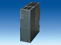
Коммуникационные модули TIM
Коммуникационные модули TIM (Telecontrol Interface Module – интерфейсный модуль телеуправления) являются основными аппаратными компонентами системы SINAUT. Они используются центральными процессорами SIMATIC S7 и компьютерными центрами управления для организации обмена данными через WAN на основе протоколов SINAUT ST1 и SINAUT ST7.
Модули TIM выпускаются в пластиковых корпусах формата S7-300 и имеют две базовые модификации:
TIM 3 без встроенного интерфейса MPI

Коммуникационные модули TIM 3 оснащены только одним встроенным портом для подключения к WAN. Они могут устанавливаться в монтажные стойки программируемого контроллера SIMATICS7-300 по аналогии с коммуникационными процессорами. Модули TIM 32/ 33/ 34 подключаются к WAN через встроенный модем. Модуль TIM 3V не имеет встроенного модема и используется в сочетании с внешним модемом, подключаемым через последовательный интерфейс.
Замечание:
Коммуникационные модули TIM 3 не могут работать в программируемых контроллерах SIMATIC S7-300 с центральными процессорами CPU 317 и CPU 318. Для этих процессоров необходимо использовать коммуникационные модули TIM 4, подключаемые через MPI.
TIM 4 с встроенным MPI интерфейсом

Коммуникационные модули TIM 4 могут устанавливаться в монтажные стойки программируемого контроллера SIMATICS7-300 по аналогии с коммуникационными процессорами или использоваться в качестве внешних устройств, подключаемых к программируемым контроллерам SIMATICS7-300/S7-400 или компьютерным центрам управления ST7cc/ST7sc через MPI.
Все модификации модулей TIM 4 оснащены двумя портами для подключения к WAN. При этом модуль TIM 4V оснащен двумя последовательными интерфейсами для подключения двух внешних модемов. Остальные модификации модулей TIM 4 оснащены одним встроенным модемом и одним последовательным интерфейсом для подключения внешнего модема.
Каждый модуль TIM 4 способен поддерживать обмен данными через два одинаковых или через различные каналы связи WAN. Например, через выделенную линию и телефонную линию.
При необходимости модуль TIM 4 может быть оснащен приемником сигналов точного времени DCF77.
Тех. данные
Дизайн
Примеры конфигураций
Ниже приведены примеры двух конфигураций, иллюстрирующих:
- установку модуля TIM 3 в монтажную стойку программируемого контроллера S7-300 по аналогии с коммуникационным процессором
- подключение модуля TIM 4 к программируемому контроллеру SIMATIC S7-400 через MPI

TIM 3 в монтажной стойке S7-300

TIM 4, подключенный к S7-400 через MPI
Модуль TIM 3 может использоваться в системе локального ввода-вывода блоков управления SIMATIC C7, оснащенных встроенным интерфейсным модулем IM 360. При этом TIM 3 устанавливается в монтажную стойку с интерфейсным модулем IM 361.

TIM 3 в системе локального ввода-вывода блока управления SIMATIC C7
Через сеть MPI один коммуникационный модуль TIM 4 способен обслуживать несколько центральных процессоров SIMATIC S7-300/ S7-400/ C7. В приведенной ниже конфигурации один модуль TIM 4 обеспечивает возможность доступа к WAN со стороны S7-400 и S7-300. Такое решение может быть использовано, например, в больших терминалах, в которых задачи автоматического управления распределены между множеством центральных процессоров.

Подключение SIMATIC S7-400 и S7-300 к модулю TIM 4 через сеть MPI
Компьютерные центры управления (например, SINAUT ST7cc или ST7sc) могут подключаться к WAN через один или несколько коммуникационных модулей TIM 4 (смотри следующий рисунок). Модули TIM 4 подключаютмя к MPI карте компьютера через встроенные интерфейсы MPI. Возможность непосредственного обмена данными между терминалами исключает необходимость последовательного включения центров управления. Центры управления других производителей, разработанные для обмена данными с SINAUT ST7 подключаются к системе тем же способом.

SINAUT ST7cc/ST7sc с несколькими модулями TIM 4, подключенными через сеть MPI
Модули TIM 3 с встроенным модемом
- TIM 32;
TIM 3 с встроенным модемом MD2 (выделенная линия)
- TIM 33;
TIM 3 с встроенным модемом MD3 (аналоговая телефонная сеть)
- TIM 34;
TIM 3 с встроенным модемом MD4 (ISDN)

Интерфейсы модулей TIM 3 с встроенным модемом
Модуль TIM 3 без встроенного модема
- TIM 3V;
с интерфейсом для подключения внешнего модема или другого приемопередающего устройства;
TIM 3V может использоваться для подключения к WAN, не поддерживаемой встроенными модемами других модификаций TIM 3. Через TIM 3V, например, может быть выполнено подключение к GSM сети, радиосети или к оптическим каналам связи.

Интерфейсы модуля TIM 3без встроенного модема
Модули TIM 4 с встроенным модемом
- TIM 42;
TIM 4 с встроенным модемом MD2 (выделенная линия)
- TIM 42D ;
TIM 4 с встроенным модемом MD2 (выделенная линия) и приемником сигналов точного времени DCF77
- TIM 43;
TIM 4 с встроенным модемом MD3 (аналоговая телефонная сеть)
- TIM 43D;
TIM 4 с встроенным модемом MD3 (аналоговая телефонная сеть) и приемником сигналов точного времени DCF77
- TIM 44;
TIM 4 с встроенным модемом MD4 (ISDN)
- TIM 42D ;
TIM 4 с встроенным модемом MD4 (ISDN) и приемником сигналов точного времени DCF77

Интерфейсы модулей TIM 4 с встроенным модемом
Модули TIM 4 без встроенного модема
- TIM 4V;
TIM 4 с двумя интерфейсами для подключения внешних модемов или других приемопередающих устройств
- TIM 4VD;
TIM 4 с двумя интерфейсами для подключения внешних модемов или других приемопередающих устройств и приемником сигналов точного времени DCF77
- TIM 4R;
TIM 4 с двумя интерфейсами для подключения внешних модемов или других приемопередающих устройств
- TIM 4RD;
TIM 4 с двумя интерфейсами для подключения внешних модемов или других приемопередающих устройств и приемником сигналов точного времени DCF77;
эти модули TIM 4 могут использоваться для подключения к WAN, не поддерживаемым встроенными модемами других модификаций TIM 4. Например, может быть выполнено подключение к GSM сети, радиосети или к оптическим каналам связи.

Интерфейсы модуля TIM 4V

Интерфейсы модуля TIM 4R
Обзор всех модулей TIM
В комплект поставки всех модулей TIM включен шинный соединитель, позволяющий устанавливать данные модули в программируемый контроллер S7-300. Модули TIM с встроенными модемами комплектуются соединительными кабелями для подключения к WAN. Модули TIM с встроенным приемником сигналов точного времени DCF77 поставляются с кабелем адаптера DCF77. Модули TIM4R/-V - с кабелем адаптера для второго интерфейса RS232/485.
| |
Работа с программируемыми контроллерами
|
MPI интерфейс
|
Количество WAN
портов
|
RS232/
RS485 для
внешнего модема
|
Модем выдел. линии MD2 3)
|
Модем аналог. тел. линии MD3 4)
|
ISDN модем MD4 5)
|
Приемник
DCF77 6)
|
Заказн. номер
|
|
|
S7-300 1)
|
S7-400 2)
|
|
TIM 3V
|
|
|
|
1
|
1
|
|
|
|
|
6NH7800-3AA00
|
|
TIM 32
|
|
|
|
1
|
|
|
|
|
|
6NH7800-3AA20
|
|
TIM 33
|
|
|
|
1
|
|
|
|
|
|
6NH7800-3AA30
|
|
TIM 34
|
|
|
|
1
|
|
|
|
|
|
6NH7800-3AA40
|
|
TIM 4V
|
|
|
|
1
|
1
|
|
|
|
|
6NH7800-4AA00
|
|
TIM 4VD
|
|
|
|
1
|
1
|
|
|
|
|
6NH7800-4AD00
|
|
TIM 42
|
|
|
|
2
|
1
|
|
|
|
|
6NH7800-4AA20
|
|
TIM 42D
|
|
|
|
2
|
1
|
|
|
|
|
6NH7800-4AD20
|
|
TIM 43
|
|
|
|
2
|
1
|
|
|
|
|
6NH7800-4AA30
|
|
TIM 43D
|
|
|
|
2
|
1
|
|
|
|
|
6NH7800-4AD30
|
|
TIM 44
|
|
|
|
2
|
1
|
|
|
|
|
6NH7800-4AA40
|
|
TIM 44D
|
|
|
|
2
|
1
|
|
|
|
|
6NH7800-4AD40
|
|
TIM 4R
|
|
|
|
2
|
2
|
|
|
|
|
6NH7800-4AA90
|
|
TIM 4RD
|
|
|
|
2
|
2
|
|
|
|
|
6NH7800-4AD90
|
1) CPU 317 и CPU 318 могут работать только с модулями TIM 4, подключаемыми через MPI.
2) Все модули TIM, рассчитанные на работу с S7-400, могут подключаться через MPI и к компьютерам с ST7cc или ST7sc.
3) С соединительным кабелем 6NH7700-2AR60 (RJ12 - RJ12) для подключения к WAN
4) С соединительным кабелем 6NH7700-3BR60 (RJ12 - RJ12 / TAE6) для подключения к WAN
5) С соединительным кабелем 6NH7700-4AR60 (RJ12 - RJ45) для подключения к WAN
6) С кабелем адаптера DCF77 6NH7700-0AD15
7) С кабелем адаптера 6NH7700-0AS05 для второго интерфейса RS232/485
Функции
Each WAN interface of a TIM can be operated with the function "Station", "Node terminal" or "Control center". the "node terminal" is not available for the TIM 3V-IE). This enables the construction of the type of hierarchical communication structures required in classic WANs.
On IP-based networks, in which each partner has equal priority, this classification can be dismissed. The transmission via GPRS however represents an exception, as without special contracts with the GPRS Provider, direct communication from GPRS station to GPRS station is not possible. This can be solved by "rerouting" through a control center TIM, as in a classic WAN with cross-traffic on a dedicated leased line or wirelessly. In this case, the interfaces of the participating TIMs are to be set to the function "Control center" or "Station" in an IP-based network as well, so that the correct path from "Station" to "Station" will be found automatically through the "Control center".
The TIM independently processes the data traffic via the network connected in each case and it does this according to the store-and-forward principle. For this purpose, the module has its own processor and a RAM for buffering data messages (depending on the type of TIM, between 10,000 and 56,000 message frames). The saving of the messages prevents a loss of data if the communication link is faulty or the partner fails. It also helps to reduce connection charges in the dialup network. If the optional backup battery is used for the TIM 4R-IE, stored data message frames are not lost in this TIM even if the 24 V supply voltage fails.
Reading and writing data that the TIM is to send or receive for a CPU can also be done with:
- TD7onCPU, the SINAUT TD7 software for the CPU, applicable to S7-300- and S7-400-CPUs as well as C7 compact control systems:
The SINAUT program in the CPU, configured with modules from the SINAUT TD7 library, acquires the process data to be transferred, checks it for changes and transfers the changes to the TIM for transmission over the WAN. Messages received without faults by the TIM via the WAN are forwarded to the local CPU. A block that has been integrated there for evaluating the specific message frame ensures that the received information is output to the outputs or data areas configured in the block.
- TD7onTIM, the SINAUT TD7 software integrated in the TIM (not present in the case of the TIM 4R / TIM 4RD), can be used with S7-300 CPUs and C7 compact control systems:
The TD7onTIM program configured by the user reads the process data to be transferred directly from the memory areas of the CPU inserted into the S7-300 rack (inputs, bit memories, DBs), checks them for changes and then transfers the changes to the send buffer of the TIM for transmission over the WAN. Data from message frames received without fault by the TIM via the WAN are directly written by the TIM into the configured memory areas of the CPU.
If required, the data acquired by "TD7onCPU" or "TD7onTIM" can be tagged with a time stamp and the "normal" or "high" priority identification for transmission over a chargeable network, e.g. dial-up or GPRS. "TD7onTIM" also allows extremely important data to be identified with the "Interrupt" priority. These have priority over all other message frames saved in the send buffer, i.e. they are transmitted before the others.
If the local SINAUT station is a control center PC (SINAUT ST7cc/ST7sc), operator inputs are recorded by the PC program, converted into SINAUT data messages according to the ST7cc/ST7sc configuration and transferred with the configured destination address to the TIM. Messages received without faults by the TIM via the WAN are forwarded to the control center PC. The ST7cc/ST7sc software evaluates the relevant message frame according to the ST7cc/ST7sc configuration.
The TIM first saves the data to be sent in its RAM buffer. The subsequent response of the TIM on sending this data is explained in the two following sections.
SINAUT communication via a conventional WAN
The response of the TIM on sending the data depends on the WAN type and the TIM function that is set on the WAN interface:
- Dedicated line, radio network;
if the interface is operated in the function "station" or "node terminal", the TIM waits to be polled by the control center before it transfers the stored data message frames. If there are no message frames available, polling is simply acknowledged.
If operated as a "control center", the TIM sends one of the message frames saved in the buffer following each completed poll + response (standard setting). If a larger number of message frames is to be sent between two polls, this can be specified when the TIM is configured.
- Dial-up network;
In "station" or "node terminal" mode, the TIM will initially not be active in the case of data with "normal" priority. In the case of data of "high" or "interrupt" priority, the TIM will immediately try to establish a link to the addressed partner in order to transfer the data. If data of "normal" priority is also available in the TIM buffer at this time, this will be transferred immediately. Data of "interrupt" priority will always be transferred first. The data of "high" and "normal" priority will subsequently be transferred in accordance with the FIFO principle, i.e. regardless of their respective priority.
If the interface is set to the "control center" function, the TIM will always try regardless of priority to establish a link to the addressed partner and to transfer the data.
Either the SINAUT ST7 protocol or the SINAUT ST1 protocol can be used for data transmission. The operating mode used depends on the type of WAN:
- Over the dedicated line and radio network, data transmission is usually performed in "Polling" mode; but in the case of two or more control centers, data is transmitted in "Multi-master polling with time slot method" (not possible with SINAUT ST1). In the radio link, the operating mode "Polling with time slot method" can be selected if required.
In both operating modes with time slot method, the interfaces of the TIM modules without DCF77 radio clock receivers can only be operated in "station" or "node terminal" mode. Only the TIM 4RD with integral radio clock receiver has the exact time onboard that is required in order to assume the "control center" interface function.
- For a dial-up network data is always transferred in "spontaneous" operating mode.
SINAUT communication via an IP-based network
For transmission via an IP-based network, a permanent S7 connection is established in each case between two TIMs or between one TIM and the ST7cc/ST7sc. The two TIMs or the TIM and ST7cc/ST7sc exchange the data packages specific to SINAUT ST7 with application of the TCP/IP transport protocol. Transmission is carried out using the S7 Communication.
When transmitting via a free-of-charge IP-based network, the data is immediately transferred to the respective partner irrespective of priority. Data is transferred in accordance with the FIFO principle. This does not apply to message frames with "interrupt" priority. These are transferred before any other message frames that are available in the buffer.
On a chargeable network, e.g. GPRS, where the amount of transmitted data is calculated, the TIM collects the small data packets as are standard with SINAUT, if they have been identified with "normal" priority, for transmission in larger blocks. This saves transmission volume because then the TCP/IP and security overhead is only required once for several SINAUT data message frames and only one acknowledgement frame is required. In this case, the TIM transfers stored "normal" message frames:
- if the collected message frames reach or exceed a size of 202 byte
- if an important message frame (priority "high" or "interrupt") is to be transferred immediately
- if the collected message frames have not yet reached a volume of 202 byte but the TCP/IP Keep-Alive Interval will soon elapse
PG communication
PG communication allows all S7 stations connected to the LAN, e.g. Industrial Ethernet, to be remotely programmed. With the aid of S7 routing it is possible to use PG communication across networks.
This cross-network PG communication also functions for the conventional and IP-based WANs used with SINAUT, because the SINAUT ST7 protocol supports the "tunneling" of PG communication. Remote programming and remote diagnosis of the SINAUT stations connected to the WAN (CPUs and TIMs) is therefore possible.
Diagnostics & service
The "SINAUT ST7 Diagnostics & Service Tool" provides comprehensive diagnostic functions and aids for commissioning and troubleshooting, e.g.:
- Operating status of the TIM
- Module status of the TIM
- General diagnostic information
- Diagnostics buffer of the TIM
- Status of the connections to local and remote communication partners (CPUs, TIMs, ST7cc, ST7sc)
- TIM message frame monitor for recording the message frame traffic
- Disabling and enabling stations in the dedicated line or wireless network, e.g. during commissioning
In addition, the TIM 3V-IE, TIM 3V-IE Advanced and TIM 4R-IE offer:
- Status and fill level of the send buffer, for each communication partner separately
- Diagnostic information regarding TD7onTIM
Also, in the case of the TIM 4R-IE:
- Disabling and enabling of stations also in the dialup network; in addition, the last station status to be set (disabled or enabled) is saved on a long-term basis so that it remains valid even after a power failure or TIM restart.
Configuration
For configuring the TIM, the "SINAUT ST7 configuration software for PG" is used. Modules from the "SINAUT TD7 module library" must be used for configuring the SINAUT program in the CPU (TD7onCPU). Both software packages are part of the SINAUT ST7 engineering software 05/2007 edition. The SINAUT ST7 configuring software can be used provided that STEP 7 V5.3 with Service Pack 2 or later has been installed.
The configuration data – like the interface functionality, addresses of the communication participants, the telephone numbers of the partner in the dial-up network, etc. – that are required in each case can be saved in the Flash EPROM on every TIM or, in the case of the TIM 4R-IE, also on the optional plug-in C-PLUG. In the case of the TIM 3V-IE and TIM 3V-IE Advanced, and when installing the TIM 4R-IE as a CP in an S7-300 or a C7 compact control system, the configuration data can also be stored on the memory card (MMC) of the CPU. The TIM can be replaced without the need for a programming device if the configuration data is saved in the CPU or in the C-PLUG.
Functional overview of all TIM versions
| |
TIM 3V-IE
|
TIM 3V-IE Advanced
|
TIM 4R-IE
|
TIM 4R
|
TIM 4RD
|
|
Can be used in conjunction with
|
|
|
|
|
|
- S7-300 and C7 compact control system
|
•
|
•
|
•
|
•
|
•
|
|
|
–
|
–
|
•
|
•
|
•
|
|
Interfaces
|
|
|
|
|
|
|
|
–
|
–
|
–
|
1
|
1
|
|
|
1
|
1
|
2
|
–
|
–
|
|
|
1
|
1
|
–
|
–
|
–
|
|
|
–
|
–
|
2
|
2
|
2
|
|
|
1
|
all
|
all
|
all
|
all
|
|
Adjustable interface function
|
|
|
|
|
|
|
|
•
|
•
|
•
|
•
|
•
|
|
|
•
|
•
|
•
|
•
|
•
|
|
|
–
|
•
|
•
|
•
|
•
|
|
Message frame memory
|
|
|
|
|
|
|
|
16000
|
32000
|
56000
|
10000
|
10000
|
|
|
–
|
–
|
•
|
–
|
–
|
|
Integrated DCF77 radio clock receiver
|
–
|
–
|
–
|
–
|
•
|
|
S7 connections via IP-based networks
|
8
|
20
|
62
|
–
|
–
|
|
Combinable with other TIMs in the S7-300 rack *)
|
–
|
•
|
•
|
•
|
•
|
|
Communication via MPI of the S7-300 CPU
|
–
|
•
|
•
|
•
|
•
|
|
TD7 library integrated in TIM (TD7onTIM)
|
•
|
•
|
•
|
–
|
–
|
|
Module replacement without PG
|
•
|
•
|
•
|
–
|
–
|
*) for each TIM a maximum of 8 connections for local communication via backplane bus
Between TIM and TIM
Between TIM and CPU (two connection resources are required for each connection with a TIM on a CPU)
Approvals
All TIM communications modules have the approvals CE, FM, ATEX, cUL508 (= UL508, CSA22.2) and cUL HazLoc.