Обзор
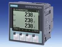
The SENTRON PAC3200 is a control panel instrument for measuring and indicating more than 50 electric power distribution variables such as voltage, current, power, electrical work and frequency with their minimum, maximum and mean values. It convinces through its compact design and high performance capacity.
A large, backlit graphic display can be read even from great distances. User-friendly, intuitive operation is made possible by plain text displays in nine languages in combination with four function buttons. Language selection is possible either directly on the device or using configuration software.
SENTRON PAC3200 offers several communication options in addition to one digital input and one digital output. For integration in a higher-level power management system it is possible to use either the integrated Ethernet interface or the optionally available expansion modules.
SENTRON PAC3200 is also available with UL and CSA approval for use in the USA and Canada.
The SENTRON powerconfig software for user-friendly device configuration is included in the scope of supply.
The product variants of the SENTRON PAC 3200
|
|
PAC3200
|
Type
|
 |
With AC/DC power supply unit with wide voltage range and screw terminals
U AUX: 95 ... 240 V AC ±10 %, 50/60 Hz
110 ... 340 V DC ±10 %
U e: max. 3 AC 690/400 V, 50/60 Hz
|
7KM2112-0BA00-3AA0
|
|
With DC power supply unit with extra-low voltage and screw terminals
U AUX: 22 ... 65 V ±10 %
U e: max. 3 AC 500/289 V, 50/60 Hz
|
7KM2111-1BA00-3AA0
|
 |
With AC/DC power supply unit with wide voltage range and cable lug terminals
U AUX: 95 ... 240 AC V ±10 %, 50/60 Hz
110 ... 340 V AC ±10 %
U e: max. 3 AC 690/400 V, 50/60 Hz
|
7KM2112-0BA00-2AA0
|
The advantages of the SENTRON PAC3200 at a glance:
- Three-phase control panel measuring device for measuring electrical variables
- Measuring more than 50 variables such as phase voltage and phase-to-phase voltage, current, power, work, power factor, frequency, etc.
- High measuring accuracy for electrical work; Class 0.5S according to IEC62053-22
- Can be used for single-phase measurements as well as for multiphase measurements in 3 and 4-conductor networks
- Can be connected directly to three-phase industrial networks up to 690/400 V or up to max. 500/289 V for devices with DC power supply unit with extra-low voltage (CATIII)
- Measuring higher voltages using a voltage transformer; adjustable transformer ratio
- For x/1A and x/5A current transformers Adjustable transformer ratio and current direction
- 2 device types available with power supply unit with wide voltage range and with extra-low voltage in order to cover all standard AC and DC auxiliary voltage supply needs
- Slot for expansion modules such as the SENTRON PAC PROFIBUS DP or SENTRON PAC RS485 communication modules
- Small space requirement thanks to compact design (96 mm x 96 mm, mounting depth 51 mm or 73 mm with module)
- Large, graphic LCD display with intuitive user operation using function buttons
- Menu selections, test displays and documentation available in nine languages (German, English, Portuguese, Turkish, Spanish, Italian, French, Chinese and Russian)
Language selection on the device or using configuration software
- IP65 using standard sealing
- Multifunctional digital input, for example for detecting counting pulses or for monitoring the status of switching devices
- Multifunctional digital output, for example for emitting active or reactive power pulses (S0) or for indicating limit value violations
- Monitoring of up to 6 limit values and connecting the limit values with logical AND / OR operations
- Measuring period averages for active and reactive power with minimum and maximum value
- Operating hours meter for indicating the load running time
- Integrated Ethernet interface (Modbus TCP or SEAbus TCP) for easy and low-cost integration in power management systems
- UL and CSA approval for the USA and Canada
- CD with SENTRON powerconfig software for user-friendly device configuration included in scope of supply

Measurement functions
The SENTRON PAC3200 measures the following variables:
|
Measured values
|
|
|
|
|
|
|
|
Variable
|
Display range
|
L1/
L1-2
|
L2/
L2-3
|
L3/
L3-1
|
Total
|
Min
value
|
Mean
value
|
Max
value
|
|
Current
|
0 A ………120 kA
|
✓
|
✓
|
✓
|
--
|
✓
|
✓1)
|
✓
|
|
Voltage L-N
|
0 V …….. 700 kV
|
✓
|
✓
|
✓
|
--
|
✓
|
✓1)
|
✓
|
|
Voltage L-L
|
0 V …..… 1200 kV
|
✓
|
✓
|
✓
|
--
|
✓
|
✓1)
|
✓
|
|
Frequency
|
44.00 … 67.00 Hz
|
✓
|
|
|
--
|
✓
|
--
|
✓
|
|
Active power per phase
input + / output -
|
0 W ….. 100 GW
|
✓
|
✓
|
✓
|
--
|
✓
|
--
|
✓
|
|
Reactive power per phase
pos./neg. or ind./cap.
|
0 var … 100 Gvar
|
✓
|
✓
|
✓
|
--
|
✓
|
--
|
✓
|
|
Apparent power per phase
|
0 VA … 100 GVA
|
✓
|
✓
|
✓
|
--
|
✓
|
--
|
✓
|
|
Active power total
input + / output -
|
0 W … 100 GW
|
--
|
--
|
--
|
✓
|
✓
|
✓2)
|
✓
|
|
Reactive power total
pos./neg. or ind./cap.
|
0 var … 100 Gvar
|
--
|
--
|
--
|
✓
|
✓
|
✓2)
|
✓
|
|
Apparent power total
|
0 VA … 100 GVA
|
--
|
--
|
--
|
✓
|
✓
|
--
|
✓
|
|
Power factor per phase
|
0 …1
|
✓
|
✓
|
✓
|
--
|
✓
|
--
|
✓
|
|
Power factor total
|
0 …1
|
--
|
--
|
--
|
✓
|
✓
|
--
|
✓
|
|
Active work total
input + / output -
|
0 Wh … 1000 GWh
|
--
|
--
|
--
|
✓3)
|
--
|
--
|
--
|
|
Reactive work total
pos./neg. or ind./cap.
|
0 varh … 100 Gvarh
|
--
|
--
|
--
|
✓3)
|
--
|
--
|
--
|
|
Apparent work total
|
0 VAh … 100 GVAh
|
--
|
--
|
--
|
✓3)
|
--
|
--
|
--
|
|
THD voltage per phase
|
0 … 100 %
|
✓
|
✓
|
✓
|
--
|
--
|
--
|
✓
|
|
THD current per phase
|
0 … 100 %
|
✓
|
✓
|
✓
|
--
|
--
|
--
|
✓
|
|
Voltage asymmetry
|
0 … 100 %
|
--
|
--
|
--
|
✓
|
--
|
--
|
--
|
|
Current asymmetry
|
0 … 100 %
|
--
|
--
|
--
|
✓
|
--
|
--
|
--
|
|
Operating hours
|
0 h … 300 years
|
--
|
--
|
--
|
✓
|
--
|
--
|
--
|
|
Universal counter
|
0 … 999,999,999 pulses
|
--
|
--
|
--
|
✓
|
--
|
--
|
--
|
1) The values quoted are mean values of all three phases.
2) Can be called up only through communication. The power averages (power count values), including minimum and maximum values, are transmitted for a selectable measurement period. The measurement period can be selected in the range 1 … 60 min; the default setting is 15 min.
3) The values for high rate and low rate are shown on the display.
✓ Measuring possible
-- Measuring not possible or not meaningful
Область применения
Three-phase multifunction measuring instruments are used to measure and indicate all relevant network parameters of an electrical installation and they monitor these parameters permanently.
Uses
Wherever power has to be distributed, be it in industrial or infrastructural buildings, the SENTRON PAC3200 supplies important information to the building services system or the power controlling system.
The many different communication options offered by the SENTRON PAC3200 make it an indispensable supplier of data for power management systems and for plant and building automation.
Industries
Power distribution systems for the power supply are needed in all industries. SENTRON PAC3200 is used accordingly in all sectors where power consumption and electrical parameters are to be measured.
Заказные данные
| Заказной № |
Вес, кг |
Описание |
Наличие на складе |
Заказать |
| 7KM2111-1BA00-3AA0 |
0.3 |
Многофункциональное измерительное устройство SENTRON PAC3200, с ЖК дисплеем, размер панели 96x96 мм, напряжение питания 22 … 65 В DC, измерительные входы Ue: макс. 3 AC 500/289 В, Ie: /1 A или /5 A, винтовые присоед. клеммы |
------ |

|
| 7KM2112-0BA00-2AA0 |
0.3 |
Многофункциональное измерительное устройство SENTRON PAC3200, с ЖК дисплеем, размер панели 96x96 мм, напряжение питания 95 … 240 В АС, 110 … 340 В DC, измерительные входы Ue макс. 3 AC 690/400 В, Ie /1 A или /5 A, клеммы для кабельных наконечников |
------ |
|
| 7KM2112-0BA00-3AA0 |
0.3 |
Многофункциональное измерительное устройство SENTRON PAC3200, с ЖК дисплеем, размер панели 96x96 мм, напряжение питания 95 … 240 В АС, 110 … 340 В DC, измерительные входы Ue макс. 3 AC 690/400 В, Ie: /1 A или /5 A винтовые присоед. клеммы |
------ |
|
Тех. данные
Особенности
- Thanks to the wide range of functions, only one device variant is required for different measuring tasks – this saves storage costs and procurement costs.
- Easy and quick mounting saves installation costs.
- Connection to power supply networks up to 690 V1) without a voltage transformer saves space in the control cabinet and costs (transformer costs, transformer mounting and installation costs).
- Comprehensive and precise power measurements form the basis for identifying savings potential in the system.
- The many different measuring and monitoring functions of the SENTRON PAC3200 contribute indirectly to a higher level of availability because faults are detected early.
- With its technical configuration, various approvals and certifications such as UL and CSA for the USA and Canada, and support for nine languages, the SENTRON PAC3200 can be used world-wide.
- A large, illuminated graphic display guarantees good reading even in poor light conditions and opens up a wider application area for the device.
- Through the multilingual, intuitive user operation of the SENTRON PAC3200, valuable time can be saved during start-up and operation.
- Thanks to the network-capable Ethernet interface, which is included without additional price in every standard device, the costs for system integration can be lowered. At the same time the high transmission speed helps to increase the performance of the overall system notably.
- The SENTRON powerconfig configuration software makes it easier to configure the devices. This results in considerable time savings, particularly when several PAC3200 units have to be configured.
- Easy integration in automation systems or power management systems, for example SIMATIC WinCC powerrate or SIMATIC PCS 7, is favored by the optional PAC PROFIBUS DP and PAC RS485 expansion modules interface, thus saving time and implementation costs.
- The SENTRON PAC3200 with its mounting depth of only 51 mm can also be installed in facilities with little depth.
1) max. 500 V (UL-L) for version with DC power supply unit with extra-low voltage (7KM2111-1BA00-3AA0).
Дизайн
Enclosures
SENTRON PAC3200 comes with a plastic enclosure for installation in control panels. It is fastened by one holder on the right side of the device and one on the left side.

Mounting the SENTRON PAC3200
To mount the SENTRON PAC3200 it is inserted from the front through the square cut-out in the control cabinet door and secured with the supplied holders.
From the front, i.e. in the installed state, the device complies with Safety Class II with degree of protection IP65.
The following picture shows how to join together the SENTRON PAC3200 and the expansion module in the light of the rear view of the SENTRON PAC3200 and the top view of the expansion module (here: PAC PROFIBUS DP).

Mounting the expansion module based on the example of the PAC PROFIBUS DP on the SENTRON PAC3200
Operating and indicating elements
The following picture shows the SENTRON PAC3200 from the front, divided into the function blocks provided for operation and monitoring, including a description.

Front of the SENTRON PAC3200
The device is operated using 4 function buttons, which correspond to the 4 text fields situated above them. The buttons are each assigned with several functions; their function at any time depends on the menu then displayed. Which function a button has in the respective menu is indicated by the text in the related display.
Функции
Precise measurement of variables
With its high accuracy, the SENTRON PAC3200 meets the increasing demand for precise power measurement. It satisfies the accuracy requirements of Class 0.5S according to IEC 62053-22 for solid-state active consumption meters.
Transparency in power matters
Altogether 10 power meters for active, reactive and apparent work monitor the power consumption in the system, separately according to the high rate and low rate, for both power input and power feedback.
This makes the SENTRON PAC3200 the optimum choice of data supplier for a higher-level power management system. Integrated in such a system it enables the user to record his installation's load profile.
For this purpose the SENTRON PAC3200 also supplies the required power averages for active and reactive power.
Plain-text displays
A large, full graphic LCD display enables easy reading even from great distances. To make sure that this is also the case in poor light conditions, the background lighting can be individually adapted to the actual requirements.
Operation, also multilingual
A special highlight is the intuitive user operation. Operation is quick to learn using the four function buttons together with multilingual plain text displays. Following languages can be selected: German, English, Portuguese, Turkish, Spanish, Italian, French, Chinese and Russian.

Operating languages of the SENTRON PAC 3200
Direct navigation is available in addition for the experienced user, who can thus call up the menus of choice even more quickly.
Mounting and start-up in the shortest possible time
With its ingenious mounting method the SENTRON PAC3200 is quick and easy to install using combination latching holders.
The pair of combination holders performs two functions:
- Thanks to the latching mechanism the fitter can fasten the device in the control panel quickly and without the use of any tools.
- If greater protection is required, the four screws of the latching holder can be used to increase its contact pressure evenly on all sides so that the control panel cut-out is cleanly sealed by the integrally molded gasket, which is a standard feature. The often bothersome and time-consuming insertion of an accessory gasket is a thing of the past.
As the result of the easy-to-use combination holders and the small mounting depth of only 51 mm it is easy to mount several devices side by side.
Powerful communication
Unique in this device class up to now is the Ethernet interface provided as a standard feature which can be used not only for configuration purposes using SENTRON powerconfig but also for system communication in a higher-level power management system. For optimum system adaptation it is possible to switch between the SEAbus TCP protocol and the Modbus TCP protocol.
Available for communication in a network are the optional SENTRON PAC PROFIBUS DP and PAC RS485 expansion modules for Modbus RTU and SEAbus.
Integration in PROFIBUS takes place using a standardized text file called the GSD (Geräte-Stammdaten-Datei). This GSD file is read into the master with the help of the PROFIBUS configuration tool. The master thus receives the slave-specific framework of the PAC3200 and can start cyclic operation immediately.
Integration in Modbus RTU or SEAbus systems takes place through parameterization of the device address and baud rate using the device keyboard or SENTRON powerconfig.
Multifunctional digital input and output
The SENTRON PAC3200 is equipped with one digital input and one digital output, to each of which various functions can be assigned.
Functions of the digital input:
- Counting input for work pulses (kWh, kvarh) from third-party devices
- Status monitoring of a switching device
- Rate switchover between high rate and low rate
- Signal input for synchronization of the measurement period
Functions of the digital output:
- Pulse output for sending work pulses (kWh, kvarh)
- Alarm output for signaling limit value violations
- SENTRON PAC3200 operating state indicator
- Phase sequence indicator
- Switching output for remote control using system software
With its wide range of functions, the SENTRON PAC3200 can be used in all applications.
Monitoring of measurement variables for limit value violations
The SENTRON PAC3200 has a function for monitoring up to 6 measurement variables for violation of an adjustable upper or lower limit value. The following variables can be monitored: voltage, current, power, power factor, THD U/I, frequency or asymmetry of voltage and current
The following can be assigned to each limit value:
- A measurement variable:
- U L-N, UL-L, IL, PL, QL, SL, LFL, THD-UL/IL for all 3 phases and UL-N, mean value, UL-L, mean value, IL, mean value, Stot, Ptot, Qtot, LFtot, frequency, asymmetry U / I
- The monitoring mode (overshooting or undershooting)
- A limit value
- A delay time and
- A hysteresis
In addition the limit values can be interconnected by an AND / OR logic function. Like the individual limit values, the result of the logic operation can also trigger certain actions.
It is possible to select the action which will be triggered by violation of a limit value. For example, a signal can be sent through the digital output or the communication interface. The integrated universal counter can be used to total the number of limit value violations. Whether a limit value has been violated is indicated on the device.
Monitoring of voltage and current for asymmetry
The device measures, among other things, the asymmetry of voltage and current in the network. Now that a limit value can also be assigned to these two parameters, problems due to unsymmetrical loads in the installation can be detected early and avoided.
Operating hours meter
An important service function is performed by the integrated operating hours counter, which can be used to monitor e.g. pumps, motors or machines. The counter measures the running time of a connected load, helping to ensure that important maintenance intervals are observed. The count can be read out and evaluated by a PC. A higher-level power management system is thus able to generate a suitable maintenance message.
Universal
The SENTRON PAC3200 can be used for measuring in two, three and four-conductor networks. It is capable of measuring in three phases as well as in one and two phases.
Thanks to its large measuring voltage range, the device can be directly connected in every low-voltage system up to a rated system voltage of 690 V (UL-L). Higher voltages can be measured using voltage transformers.
For measuring currents it is possible to use both x/1A and x/5A current transformers. Transformer ratios and current direction can be programmed on the device for adaptation to local conditions.
Protection against unauthorized access
The SENTRON PAC3200 comes with integrated password protection so that the power and parameter data are safe from unauthorized access. Changes to the parameterization can be traced using a configuration counter which can be read out through an interface.
Интеграция
Using the interface modules it is possible to integrate the SENTRON PAC3200 in every I&C system or every SIMATIC S7 environment.
When the SENTRON PAC3200 is fully integrated in a power management system, e.g. SIMATIC WinCC powerrate or SIMATIC PCS 7 powerrate, it monitors the power consumption.
At the same time the SENTRON PAC3200 helps to monitor the operating state of the installation. Measured values, limit value violations, operating hours of a connected load or power flows are supplied by the device quickly and reliably.

Integration of the SENTRON PAC3200 in SIMATIC PCS 7 / WinCC powerrate
Конфигурация
The SENTRON PAC3200 is designed for user-friendly configuring directly on the device. All menus are displayed in plain text and are largely self-explanatory. Thanks to the uniform and simple programming scheme, configuring is straightforward even without a manual.

Configuring interface of the SENTRON PAC3200
Configuring with SENTRON powerconfig is user-friendly
The scope of supply of the PAC3200 includes the SENTRON powerconfig software for the user-friendly configuring of the PAC3200 from the PC.
The software runs on the following operating systems:
- Windows 2000 Professional SP4 and higher
- Windows XP Professional SP2 and higher
SENTRON powerconfig is available in German or English, with selection possible at any time through the Options menu. The integrated online help is likewise bilingual and describes the software's functions in detail.
After SENTRON powerconfig is installed, the PAC3200 can be connected to the PC in two ways:
- using a commercially available crossover cable which connects the PAC3200 directly to the network interface of the PC
- or using a hub/switch in an Ethernet network. In this case conventional patch cables are used.
Direct connection between the PC and PAC3200

Direct connection between the PC and PAC3200

Connection between the PC and PAC3200 through a hub/switch
Note: The required cable material is not included in the scope of supply.
Simplified making of connections through search function
SENTRON powerconfig comes with a search function which facilitates the finding of all PAC3200 units connected to the same network. Making the first connection is thus easier. Both the communication status and the configuration status are indicated by symbols in the tree view.
Configuration management
With the project manager in SENTRON powerconfig it is possible to save device configurations and also to copy them if required.
For the documentation of device configurations, SENTRON powerconfig has a user-friendly printing function with preview feature.
Off-line device configurations
Using the offline device configurations, all the devices of a plant can be configured in the comfort of the office as follows:
- Creating the offline device configurations: All available devices and expansion modules are grouped in a library. The required PAC3200 units are selected from the library and moved into the device tree by means of Drag & Drop.
Expansion modules can be added to the device tree in the same way. However, they can only be entered under a device.
- Sending the offline device configurations: During start-up, the offline device configurations can be sent to the devices as soon as they are connected to SENTRON powerconfig.
User interface of SENTRON powerconfig
The individual subwindows can be positioned on the monitor as required, including outside the main window of SENTRON powerconfig. In this way the interface of the software can be adapted to the user's individual preferences.
The figure below shows the program interface of SENTRON powerconfig by way of example.
Технические данные
|
Measurement
|
|
|
|
|
Networks
|
|
|
Only for alternating voltage systems
|
|
Voltage types
|
|
|
1, 2 or 3-phase
|
|
Number of phases
|
|
|
3- or 4-conductor networks
|
|
Number of conductors
|
|
|
Same or any load
|
|
Quadrants
|
|
|
4 quadrants (input and output)
|
|
Frequency of fundamental wave
|
|
Hz
|
50/60
|
|
Signal detection
|
For power, current and voltage
|
|
Seamless
|
|
Curve shape
|
|
|
Sinusoidal or distorted
|
|
Measuring inputs for voltage
|
|
|
|
Rated voltage 3 AC Ue (max.)
|
|
|
|
Device with 7KM2112-0BA00-3AA0 or
7KM2112-0BA00-2AA0 AC/DC power supply unit with wide voltage range
|
Phase/N
|
V AC
|
400 (max. 347 for UL) +20 %
|
|
Phase/phase
|
V AC
|
690 (max. 600 for UL) +20 %
|
|
Device with 7KM2111-1BA00-3AA0 DC power supply unit with extra-low voltage
|
Phase/N
|
V AC
|
289 +20 %
|
|
Phase/phase
|
V AC
|
500 + 20 %
|
|
Measuring category
|
|
|
CAT III
|
|
Input resistance
|
Phase/N
|
MΩ
|
1.05
|
|
Power consumption
|
Per phase
|
mW
|
220
|
Measuring of voltages > 690 V AC using voltage transformer
|
Measuring inputs for current
|
(only using current transformer)
|
|
|
|
Rated current 3 AC Ie per phase
|
Adjustable
|
AC A
|
1 or 5
|
|
Operating range current per phase
|
With setting 1A
|
AC A
|
0.01 ... 1.2
|
|
|
With setting 5A
|
AC A
|
0.05 … 6
|
|
Permanent load capacity
|
Permanent
|
AC A
|
10
|
|
Surge overload capability
|
For 1 second
|
AC A
|
100
|
|
Power consumption
|
Per phase
|
mVA
|
4 at 1A
115 at 5A
|
|
Measuring category
|
|
|
CAT III
|
|
Zero point suppression
|
Adjustable
|
%
|
0 … 10
|
|
Supply voltage
|
|
|
|
|
Power supply unit with wide voltage range
|
|
|
AC / DC
|
|
Operating range
|
7KM2112-0BA00-3AA0 or 7KM2112-0BA00-2AA0
|
V AC
|
95…240 ±10%
|
|
|
|
V DC
|
110…340 ±10%
|
|
Rated frequency
|
|
Hz
|
50/60
|
|
Power supply unit with extra-low voltage
|
|
|
DC
|
|
Operating range
|
7KM2111-1BA00-3AA0
|
V DC
|
22 … 65 ±10%
|
|
Power consumption
|
|
|
DC
|
|
Without optional expansion module
|
VA
|
6
|
|
With optional expansion module
|
VA
|
8
|
|
Overvoltage category
|
|
CAT III
|
|
Fault limits
|
|
|
|
|
Voltage
|
|
%
|
± 0.3
|
|
Current
|
|
%
|
± 0.2
|
|
Rating
|
|
%
|
± 0.5
|
|
Frequency
|
|
%
|
± 0.05
|
|
Power factor
|
|
%
|
± 0.5
|
|
Active energy
|
|
|
Class 0.5S
according to IEC 62053-22:2003-01
|
|
Reactive energy
|
|
|
Class 2
according to IEC 62053-23:2003-01
|
|
When taking measurements on external current or voltage transformers, the accuracy of the measurements depends on the quality of the transformers.
|
|
Digital input
|
|
|
|
|
Qty
|
|
|
1
|
|
Rated value
|
|
V DC
|
24
|
|
Max. input voltage
|
|
V DC
|
30
|
|
Switching threshold signal "1"
|
|
V DC
|
> 13
|
|
Switching threshold signal "0"
|
|
V DC
|
< 8
|
|
Input current signal "1"
|
|
DC mA
|
7
|
|
Digital output
|
|
|
|
|
Qty
|
|
|
1
|
|
Required voltage
|
|
V DC
|
12 … 24
|
|
Max. switched output voltage
|
|
V DC
|
30
|
|
Output current signal "0"
|
|
DC mA
|
Max. 0.2
|
|
Output current signal "1"
|
Typical
|
DC mA
|
10 … 27
|
|
|
Permanent
|
DC mA
|
100
|
|
|
Short-time overload for max. 100 ms
|
DC mA
|
300
|
|
|
Resistive load
|
DC mA
|
100
|
|
Switching frequency
|
|
Hz
|
17
|
|
Short-circuit protection
|
|
|
Yes
|
|
Communication
|
|
|
|
|
Ethernet
|
|
|
RJ45 socket
|
|
Interface integrated
|
|
MBit/s
|
10
|
|
Protocol
|
|
|
Optionally SEAbus or Modbus RTU (selectable)
|
|
PROFIBUS DP
|
|
|
9-pole Sub D socket
|
|
Using expansion module
|
PAC PROFIBUS DP
|
|
|
|
Transmission rate max.
|
|
MBit/s
|
12
|
|
Protocol
|
|
|
PROFIBUS DPV1
|
|
Variables to be transmitted
|
|
|
Definable using GSD file
|
|
RS 485
|
|
|
|
|
Using expansion module
|
PAC RS485
|
|
|
|
Transmission rate max.
|
|
kBd
|
Optionally 4.8 /9.6 /19.2 / 38.4
|
|
Protocol
|
|
|
Optionally SEAbus or Modbus RTU (selectable)
|
|
Indicating and operating
|
|
|
|
|
Display type
|
Type
|
LCD
|
Full graphic
|
|
Displays
|
|
|
Alphanumeric and text
|
|
Resolution
|
|
Dots
|
128 x 96
|
|
Size
|
|
mm
|
72 x 54
|
|
Contrast
|
|
|
Adjustable
|
|
Display
|
Display invertible
|
|
pos. / neg. mode
|
|
Background lighting
|
Lighting intensity
|
|
Adjustable
|
|
|
Lighting intensity dimmed
|
|
Adjustable
|
|
|
Dimming time
|
min
|
0…99
|
|
Languages
|
|
|
German, English, Portuguese, Turkish, Spanish, Italian, French, Chinese and Russian
|
|
Connection elements and terminals
|
|
|
|
Measuring inputs and supply voltage
|
|
|
Screw terminals
|
|
Conductor cross-sections
|
Solid
|
mm2
|
1 x 0.5 … 4
|
| |
|
|
AWG 1 x 20 … 12
|
|
|
mm2
|
2 x 0.5 … 2.5
|
|
|
|
AWG 2 x 20 … 14
|
|
Finely stranded with end sleeve
|
mm2
|
1 x 0.5 … 2.5
|
|
|
|
AWG 1 x 20 … 12
|
|
|
|
mm2
|
2 x 0.5 … 1.5
|
|
|
|
|
AWG 2 x 20 … 16
|
|
Tool size
|
± screw, Pozidriv
|
|
2
|
|
Measuring inputs and supply voltage
|
|
|
Ring terminal lug connections
|
|
Conductor cross-sections
|
Dependent on ring terminal lug used
|
mm2
|
1 x 1.0 … 6
|
| |
|
|
AWG 1 x 18 … 10
|
| |
 |
mm
|
D: 3...4
S: 0.75 ... 1.0
W: ≤ 8
L1 ≤ 24
L2 ≤ 20
L3 ≥ 8
|
|
Inch
|
D: 0.118 ... 0.157
S: 0.029 ... 0.039
W: ≤ 0.314
L1: ≤ 0.944
L2: ≤ 0.787
L3: ≥ 0.314
|
| |
|
|
|
|
Tool size
|
± screw, Pozidriv
|
|
2
|
|
Digital output, digital input
|
|
|
Screw terminals
|
|
Conductor cross-sections
|
Solid
|
mm2
|
1 x 0.2 … 2.5
|
 |
|
mm2
|
2 x 0.2 … 1.0
|
|
|
|
AWG 1 x 24 … 12
|
|
Finely stranded with end sleeve
|
mm2
|
1 x 0.25 … 2.5
|
|
|
|
|
2 x 0.25 … 1.0
|
|
|
|
|
AWG 1 x 24 … 12
|
|
Tool size
|
± screw, Pozidriv
|
|
2
|
|
Dimensions and weights
|
|
|
|
|
Enclosure for installing in control panel
|
|
|
According to IEC 61554
|
|
Enclosure dimensions
(W x H x D)
|
Without expansion module
|
mm
|
96 x 96 x 56
|
|
|
With expansion module
|
mm
|
96 x 96 x 78
|
|
Mounting depth
|
Without expansion module
|
mm
|
51
|
|
|
With expansion module
|
mm
|
73
|
|
Control panel thickness
|
|
mm
|
0.5 … 4 mm
|
|
Weight
|
Without expansion module
|
g
|
approx. 325
|
|
|
With expansion module
|
g
|
approx. 370
|
|
Degree of protection / safety class
|
|
|
|
|
Safety class according to EN 61010-1
|
From the front when installed
|
|
II
|
|
Degree of protection according to EN 60529
|
Mountable on front
|
|
IP65
|
|
|
Device with screw terminals at the rear
|
|
IP20
|
|
|
Device with cable lug terminals at the rear
|
|
IP10
|
|
Ambient conditions
|
|
|
|
Temperature range
|
Operating temperature
|
°C
|
‑10 … +55
|
|
|
Storage and transport temperature
|
°C
|
‑25 … +70
|
|
Relative air humidity
|
At 25 °C without condensation
|
%
|
95
|
|
Operating altitude
|
Above sea level up to max.
|
m
|
2000
|
|
Degree of pollution
|
|
|
2
|
|
Safety
|
|
|
|
|
Password protection
|
|
|
4-digit numeric code
|
|
Safety requirements
|
Verification of suitability as EC conformity declaration - Device test according to the following standards
|
|
IEC 61010-1:2001 (2nd Ed.) with Corr. 1
EN 61010-1-1:2001 (2nd Ed.)
DIN EN 61010-1:2002 with Corr. 1
|
|
Verification of suitability as approval for the USA and Canada
|
|
UL 61010-1, 2nd Ed. CAN/CSA-C22.2 NO. 61010-1-04 1
|
|
Electromagnetic compatibility
|
|
|
|
Emitted interference
|
|
|
IEC 61000-6-4 Group 1; Class A
|
|
|
|
|
CISPR11 Group 1; Class A
|
|
|
|
|
FCC Part 15 Subpart B; Class A
|
|
Enclosure interference immunity
|
Electrostatic discharge
|
|
IEC 61000-4-2:2001-04
|
|
|
Electromagnetic fields
|
|
IEC 61000-4-3:2006-02
|
|
|
Line-frequency magnetic fields
|
|
IEC 61000-4-8:2001-03
|
|
Measuring and supply voltage
|
Voltage dips
|
|
IEC 61000-4-11:2004-03
|
|
|
Rapid transients
|
|
EN 61000-4‑4:2005-07
|
|
|
Surge voltages
|
|
EN 61000-4-5:2001-12
|
|
|
Line-conducted RF signals
|
|
EN 61000-4-6:2001-12
|
|
Inputs and outputs, interfaces
|
Rapid transients
|
|
IEC 61000-4-4:2004-07
|
|
|
Surge voltages
|
|
IEC 61000-4-5:2005-11
|
|
|
Line-conducted RF interference fields
|
|
EN 61000-4-6:2001-12
|
|
Mechanical dynamic stress
|
|
|
|
Vibratory load)
|
Use and transport conditions
|
|
According to IEC 60068 Part 2-6:1995‑03 /
EN 60068 Part 2-6:1996-05
|
|
Seismic stress
|
|
|
According to IEC 60068 Part 3-3:1991-02 / EN 60068 Part 3-3:1993-09
|
|
Shock stress
|
|
|
According to IEC 60068 Part 2-27:1987 / EN 60068 Part 2-27:1995-03
|
|
Bumping, resistance
|
|
|
According to IEC 60068 Part 2-27:1987 / EN 60068 Part 2-27:1995-03
|
|
Continuous bumping
|
|
|
According to IEC 60068-2-29:1987 /
EN 60068 Part 2-29:1995-03
|
|
Mechanical strength
|
Against surges and shocks
|
|
According to IEC 60068-2-75:1997-08
|
Тех. данные 2
Чертеж
Dimensions of multifunction measuring instrument

Left: Front view
Middle: PAC3200 with screw terminals, view from the right
Right: PAC3200 with cable lug terminals, view from the right
Control panel cut-out

Cut-out from the front
Control panel cut-out, lateral

Left: PAC3200 with screw terminals, view from the right
Right: PAC3200 with cable lug terminals, cut-out from right
Mounting clearances

Схема подключения
Connection examples
Connection example 1:
Three-phase measurement, four conductors, asymmetric load, without voltage transformer, with three current transformers

Connection example 2:
Three-phase measurement, four conductors, asymmetric load, with voltage transformer, with three current transformers

Connection example 3:
Three-phase measurement, four conductors, symmetric load, without voltage transformer, with one current transformer

Connection example 4:
Three-phase measurement, four conductors, symmetric load, with voltage transformer, with one current transformer

Connection example 5:
Three-phase measurement, three conductors, asymmetric load, without voltage transformer, with three current transformers

Connection example 6:
Three-phase measurement, three conductors, asymmetric load, with voltage transformer, with three current transformers

Connection example 7:
Three-phase measurement, three conductors, asymmetric load, without voltage transformer, with two current transformers

Connection example 8:
Three-phase measurement, three conductors, asymmetric load, with voltage transformer, with two current transformers

Connection example 9:
Three-phase measurement, three conductors, symmetric load, without voltage transformer, with one current transformer

Connection example 10:
Three-phase measurement, three conductors, symmetric load, with voltage transformer, with one current transformer

Connection example 11:
Two-phase measurement, three conductors, asymmetric load, without voltage transformer, with two current transformers

Connection example 12:
Single-phase measurement, two conductors, without voltage transformer, with one current transformer

Connection example 13:
Three-phase measurement, four conductors, asymmetric load, with voltage transformer, with three current transformers

*) Fuses must be provided by the user.
**) Connection of the supply voltage.
Fusing of the supply voltage input:
|
Fuse holders
|
Cylindrical fuse links
|
|
Fuse holders
|
3NW1006-0HG (0.6A)
|
Connection graphics


Дальнейшая информация