Тех. данные
Особенности
The in-situ SITRANS SL gas analyzer features high operational availability, unique analytical selectivity, and a wide range of possible applications. SITRANS SL permits measurement of a gas component directly in the process:
- With high dust load
- In hot, humid, corrosive, explosive, or toxic gases
- In applications showing strong varying gas compositions
- Under harsh environmental conditions at the measuring point
- Highly selective, i.e. mostly without cross-sensitivities
Special features of the SITRANS SL:
- Little installation effort
- Minimum maintenance requirements
- Extremely rugged design
- High long-term stability through built-in, maintenance-free reference gas cell
- Real-time measurements
Moreover, the analyzer provides warning and error messages:
- When maintenance is required
- With large variations in the reference signal
- With poor signal quality
- If the transmission violates an upper or lower limit
Дизайн
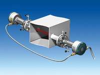
The SITRANS SL gas analyzer consists of a pair of cross-duct sensors - a transmitter unit and a receiver unit - both with the same dimensions. The complete analyzer is integrated in these two enclosures. The transmitter unit contains the laser source whose light is transmitted to the receiver through the measurement path. The receiver unit contains a photodetector including electronics as well as a reference cell. The receiver unit is connected to the transmitter unit by means of a sensor cable. A further cable on the receiver is used to connect the power supply and the communication interfaces. The receiver enclosure contains a local user interface (LUI) with an LC display which can be read through a window in the cover. The LUI is operated by remote-control.
Transmitter and receiver units
Special features of the transmitter and receiver units:
- In-situ cross-duct sensors, designed as transmitter and receiver units, connected via sensor cable
- Powder-coated aluminium; stainless steel
- Degree of protection IP65
- Adjustable flanges
- DN 50/PN 16, ANSI 4"/150 lbs
- Purging facilities on the process and the sensor sides, configurable application with purging gas connections for nitrogen
- Optional: Ex-protected version in accordance with ATEX II 2 G Ex de op is IIC T6 / II 2 D Ex tD A21 IP 65 T85°C

SITRANS SL, receiver unit
Parts wetted by the process gas
Only the stainless steel and borosilicate window flange of the sensor is wetted by the process gas. This has optional connections for purging the process gas side with an appropriate gaseous medium.
Display and control panel
Special features of the receiver unit:
- Display for simultaneous output of result and device status
- LED backlighting of display
- Remote operation using membrane keypad and softkeys which are easy to clean
- Menu-driven operation for parameterization and diagnostics
- Remote operation via infrared interface for safe use in EEx zones

Local user interface (LUI) of SITRANS SL in the receiver unit (display of measured value)

Remote control keypad for SITRANS SL
Connection cables
The sensor cable connects together the transmitter and receiver units of the analyzer. All materials are flame-retardant.
For non-EEx environments, the SITRANS SL is provided with two 1-m long adapter cables which are already connected to the transmitter and receiver units. By using a sensor cable between the two adapter cables, the cable lengths can be increased by a further 5, 10 or 25 m.
A rugged cable sleeve should be used as UV protection for installations in open cable ducts or channel systems.
The statutory directives must be observed in the event of installation in EEx environments.
The EEx version of the SITRANS SL is provided with a 3-m cable which is already connected to the receiver unit, as well as a 5, 10 or 25-m sensor cable which is already connected to the transmitter unit, where EEx connectors are used at the transmitter and receiver ends. The connection between the two sensor cables must be made in an EEx junction box.
Inputs/outputs
- 2 analog inputs (4 to 20 mA) for process gas temperature and pressure
- 2 analog outputs (4 to 20 mA) for gas concentration or for concentration and transmission
- 2 configurable binary inputs
- 2 freely-configurable binary outputs (display of faults, maintenance requirement, function monitoring, alarms for limit violations of measured value or transmission)
- Optional: 1 PROFIBUS DP interface with:
- Output of concentration as cyclic data
- Alarm output, alarm classification
- Input for temperature and/or pressure data for compensation
The PROFIBUS DP protocol provides DPV0, cyclic data. Measured values are provided with additional quality data.
- 1 Ethernet 10Base-TX port, only for servicing and maintenance. Over Ethernet, the analyzer supports:
- LDSCom
- SITRANS SL updater (RSM client)
Note:
In contrast to the other interfaces, the Ethernet port is only accessible following removal of the receiver unit cover. With EEx versions, the Ethernet connection is available for temporary use via the cable.
CAUTION:
In an EEx environment, Ethernet connections may only be made or removed with the permission of the plant owner!
Функции
Operating principle
SITRANS SL is a gas analyzer employing single-line molecular absorption spectroscopy. A diode laser emits a beam of infrared light which passes through the process gas and is detected by a receiver unit. The wavelength of the laser diode output is tuned to a gas-specific absorption line. The laser continuously scans this single absorption line with a very high spectral resolution. The degree of absorption and the line shape are used for the evaluation. The measurement is free of cross-interferences, since the quasi-monochromatic laser light is absorbed very selectively by only one specific line in the scanned spectral range.

Basic design of the SITRANS SL
The field design of the SITRANS SL in-situ gas analyzer consists of a transmitter unit and a receiver unit. The light which is not absorbed by the sample is detected in the receiver. The concentration of the gas component is determined from the absorption.
The SITRANS SL analyzer measures a single gas component by means of the absorption capacity of a single fully resolved molecular absorption line.

Absorption spectrum of oxygen
SITRANS SL is designed for measuring oxygen (O2).
Typical application specifications:
|
Oxygen concentration
|
0 ... 21 vol%
|
|
Process pressure/temperature conditions
|
700 ... 5 000 hPa (absolute)/0 ... 200 °C
900 ... 1 100 hPa (absolute)/0 ... 600 °C
|
The individual dependencies of concentration, pressure and temperature are application-specific.
An internal reference cell is used to constantly check the stability of the spectrometer.
The self-calibration of the analyzer is therefore valid for at least one year without the necessity for external recalibration using calibration gases.

Typical spectral bandwidth of an absorption line compared to the bandwidth of the laser light.
Configuration
A feature of the in-situ analytical procedure is that the physical measurement takes place directly in the stream of process gas and directly in the actual process gas line. All process parameters such as gas matrix, pressure, temperature, moisture, dust load, flow velocity and mounting orientation can influence the measuring properties of the SITRANS SL and must therefore be investigated for each new application.
The standard applications listed in the ordering data for the SITRANS SL are distinguished in that the typical process conditions are adequately well-known and documented. If you cannot find your application among the standard applications, please contact Siemens. We will be pleased to check your possible individual application of the SITRANS SL. You can find an application questionnaire on the SITRANS SL product site on the Internet.

Typical cross-duct arrangement of the SITRANS SL
Nitrogen is used as purging gas to prevent contamination of the sensor optics on the process side. Purging tubes on the sensor heads, which slightly extend into the process gas stream, define the effective measuring path length.
Influences on the measurement
Dust load
As long as the laser beam is able to generate a suitable detector signal, the dust load in the process gas does not influence the analytical result. By applying a dynamic background correction, measurements can be carried out without any negative impact. Under optimum conditions, the SITRANS SL can cope with dust loads up to 20 g/Nm3. The influence of a high dust load is extremely complex, and depends on the optical path length and particle size. The optical damping increases exponentially at longer path lengths. Smaller particles also have a very large influence on the optical damping. With high dust load, long path length and small particle size, the technical support at Siemens should be consulted.
Temperature
The temperature influence on the absorption line is compensated by a correction file which is produced during initial calibration of the analyzer. A temperature signal can be fed into the instrument from an external temperature sensor. The signal is then used for mathematical correction of the influence of the temperature on the observed line strength. If the process gas temperature remains constant, a static correction can be carried out as an alternative. Without temperature compensation, the relative error caused by changes in the gas temperature has an extensive effect on the measurement of up to 0.24 %/K. An external temperature signal is therefore recommended in most cases.
Pressure
The process gas pressure can affect the line shape of the molecular absorption line. For known pressure values, the SITRANS SL uses a special algorithm to adapt the line shape. Additionally, an external pressure signal can be fed to the instrument to provide complete mathematical compensation for the pressure influence including the density effect. Without compensation, the relative error caused by changes in the process gas pressure is approx. 0.1 %/hPa. An external pressure signal is therefore recommended in most cases.
Interferences
Since the SITRANS SL derives its signal from a single fully resolved molecular absorption, interferences from other gases are quite unlikely. The SITRANS SL is therefore able to measure the desired gas components very selectively. In special cases, the composition of the process gas might have an influence on the shape of the absorption lines. This influence is compensated by analyzing the full shape of the detected signal curve applying specific algorithms.
Optical path length
As a result of Beer-Lambert's law, the absorption of laser light depends on the optical path length within the gas. Therefore the precision of the optical path length measurement can have an effect on the precision of the total measurement.
Since the sensor optics on the process side usually has to be purged to keep it clean for a longer period, the extent of the mixed zone between the purging medium and the process gas as well as the latter's concentration distribution must be considered. In a typical in-situ installation with an optical path length of several meters, the influence of the purging gas on the effective path length can be ignored.
The path length and dust load are mutually influencing: the higher the dust load in the process, the shorter the max. possible path length.

Design of the non-EEx version of the SITRANS SL system

Design of the EEx version of the SITRANS SL system
The transmitter and receiver units are mounted on process flanges provided by the customer. Correct alignment of these flanges must be guaranteed, e.g. by using the optional sensor alignment kit.
Adjustment of the pair of sensors
The process flanges of the SITRANS SL must be correctly aligned so that the laser beam generated by the transmitter hits the photodetector in the receiver unit. This is guaranteed in that the transmitter and receiver units have a curved surface integrated in the flanges. The adjustment is carried out by shifting the flanges on these surfaces, through which the symmetry axis is aligned. The axis can be offset by ±1 degree, which means that the process flanges must be welded onto the process wall with at least this accuracy - see following figure.

Installation/adjustment requirements for the pair of cross-duct sensors
Purging
The easiest way to avoid condensation and dust deposits on the sensor windows is to purge them, e.g. with nitrogen. Purging must be selected depending on the application. The transmitted-light sensors can therefore be configured for the respective situation. The application reference table provides recommendations for suitable purging for the standard applications.
Since oxygen is to be measured with the SITRANS SL - which is also present in measurable quantities in the ambient air - oxygen-free purging gas is must be used, such as nitrogen. It is equally necessary to purge the inside of the sensor heads, since the ambient air must also be displaced here out of the laser beam path. A differentiation is therefore made between purging on the process side and purging on the sensor side.

Arrangement for purging on the sensor side of the SITRANS SL
Purging on process side
For purging on the process side, the flow of purging gas can be adjusted between 0 and approx. 50 l/min at each sensor head using a needle valve (included in delivery).
Purging on sensor side
This can be combined with the purging with nitrogen on the process side, and is always required for applications with oxygen. The cells in the sensor head are then continuously purged with nitrogen. The flow of purging gas required in this case is approx. 3 to 5 l/min and can be set using a needle valve (included in delivery).
Purging tubes
The purging media used on the process side flow through purging tubes into the process gas stream. The tubes extend into the process area by a few centimeters, usually perpendicular to the process gas stream. This means that an exactly defined optical path length is defined through the sample gas. The effective measuring path in the process gas is therefore defined as the distance between the ends of the two purging tubes. The standard length of the purging tubes is 340 mm. To enable sufficient pivoting, the process wall should be max. 150 mm thick.

Measurement of the optical path length between the ends of the purging gas tubes
Maintenance and fault messages
The SITRANS SL carries out continuous self-monitoring, and outputs alarms and warnings to indicate maintenance requirements or a system fault. The information is output as plain text on the LUI display, where symbols identify the category and the severity of the fault.
Alarm categories:
- Maintenance (system must be cleaned or repaired)
- Process value (problem with external sensor, or process conditions outside the permissible range for SITRANS SL)
- Configuration (SITRANS SL is not correctly configured)
Severity:
- Fault (measurements could not be carried out)
- Warning (measurements may be inaccurate, or the system will soon shut down measuring mode if an intervention is not made)
- Advanced warning/information (measurements are carried out)
The two binary (relay) outputs can be configured freely for the alarm output.
The response of the analog outputs in the event of an alarm is configurable; possible actions are:
- Off (current measured value is displayed)
- Last measured value (freezing of last value displayed)
- Standard level (setting to predefined value)
- 3 mA (Namur NE43 fault status)
In addition, the transmission is available as an output variable.
Note
Specific requirements for the measuring point can make the utilization of special sensor equipment necessary. The possibilities for adapting the sensors are:
- Special materials for purging tubes (on request)
- Various types/sizes of sensor flanges
- EEx-proof sensor configurations
Essential characteristics
- Long-term stability through use of an internal reference cell; calibration interval at least one year
- Dynamic background correction for varying dust loads
- Isolated signal outputs of 4 to 20 mA
- User-friendly, menu-driven operation
- Selectable time constants (response time)
- Password-protected user interface
- I/O operation in accordance with NAMUR recommendations
- Monitoring of overall optical transmission
- Sensor enclosure resistant to wear and corrosion
- Simple local operation using remote-control unit with numeric keypad and menu prompting
Технические данные
|
Analytical performance
|
|
|
Measuring range
|
Internally adjustable
|
|
Detection limit at standardized conditions:
25 °C gas temperature, 1000 hPa, 1 m path length, 3 s integration time and constant ambient conditions. Calculated in accordance with VDI 2449.
|
O2: 200 ppm
|
|
The maximum and minimum measuring ranges which can be used are listed in the table of standard applications for SITRANS SL. These can only be used if the specific process conditions allow.
|
|
Accuracy (at standardized conditions)
|
2 % of measured value or detection limit (the higher value applies)
|
|
Linearity error (at standardized conditions)
|
< 1 %
|
|
Precision (at standardized conditions)
|
2 % of measured value or detection limit (the higher value applies)
|
|
Zero point drift
|
Negligible
|
|
Measured-value drift
|
Less than 4 % of measured value over 12 months
|
|
General
|
|
|
Design
|
Transmitter and receiver units, connected by a sensor cable
|
|
Materials
|
Sensor enclosure: treated aluminium/stainless steel
Process interface: acid-resistant stainless steel
Window: hardened borosilicate glass
|
|
Installation
|
In-situ or bypass
|
|
Concentration units
|
ppm, vol%, mg/Nm3
|
|
Display
|
Digital concentration display (4 digits with floating decimal point)
|
|
Laser protection class
|
Class 1, safe to the eye
|
|
EEx protection
|
Optional, in accordance with ATEX II 2 G Ex de op is IIC T6 / II 2 D Ex tD A21 IP 65 T85°C
|
|
Design, enclosure
|
|
|
Degree of protection
|
IP65 in accordance with EN 60529
|
|
Dimensions
|
For each unit (transmitter, receiver)
- Diameter: 165 mm
- Length: 357 mm
|
|
Purging tube
|
Length, outer diameter, inner diameter:
340, 48, 44 mm
|
|
Weight
|
- Receiver unit*) 11.3 kg
- Transmitter unit*) 10.5 kg
*) Incl. process interface (5.3 kg for PN 16 flange)
|
|
Mounting/process interface
|
DN 50/PN 16 or ANSI 4"/150 lbs
|
|
Electrical characteristics
|
|
|
Power supply
|
19.5 ... 30.2 V DC
|
|
Maximum power consumption
|
10 W
|
|
EMC
|
In accordance with EN 61326
|
|
Electrical safety
|
In accordance with EN 61010-1
|
|
Fuse specifications
|
Recommended: 1.5 A (slow-blow)
|
|
Dynamic performance
|
|
|
Warm-up time at 20 °C ambient temperature
|
Start of measurement: < 5 min.
Full accuracy for O2: < 60 min.
|
|
Response time (T90)
|
Approx. 1 s, depends on application
|
|
Integration time
|
2 ... 100 s, selectable
|
|
Influencing variables
|
|
|
Variations in ambient temperature
|
< 0.5 % of measured value/10 K
|
|
Process gas temperature
|
With compensation: < 1 % of measured value/100 K
|
|
Variations in ambient pressure
|
Negligible
|
|
Process gas pressure
|
With compensation: < 0.25 % of measured value / 1 000 hPa
|
|
Variations in supply voltage
|
Negligible
|
|
Electrical inputs and outputs
|
|
|
Number of measurement channels
|
1
|
|
Analog outputs
|
2 outputs, 4 ... 20 mA, floating, ohmic resistance max. 900 Ω. External isolating power supplies may have to be provided by the customer.
|
|
Analog inputs
|
2 inputs, designed for 4 ... 20 mA
|
|
Binary outputs
|
2 outputs, with switchover contacts, configurable, 24 V/0,5 A, floating, single pole double throw (SPDT)
|
|
Binary inputs
|
2 inputs, designed for 24 V, floating, configurable
|
|
Service port
|
Ethernet 10BaseT (RJ-45)
|
|
RS-485/Profibus
|
Two-wire interface, up to 12 MB/s, -7 ... 12 V
|
|
Connection cable to customer interface
|
|
|
Cable type
|
Two-wire copper cable
|
|
Plug-in connector
|
- Non-EEx: TrimTrio 23-pin
- EEx digital bus: junction box available as accessory
|
|
Cable length
|
- Non-EEx: 2 x 0.5 m
- EEx digital bus: 3 m
|
|
Minimum bending radius
|
- Non-EEx - analog: 60 mm
- Non-EEx - Profibus: 30 mm
- EEx - Profibus: 100 mm
|
|
Sensor cable
|
|
|
Sensor cable type
|
Two-wire copper cable, in twisted pair configuration, for +24 V power supply of detector electronics.
|
|
Plug-in connector
|
- Non-EEx: TrimTrio 8-pin
- EEx: screw terminals in junction box
|
|
Cable sheath
|
PVC
|
|
Dimensions
|
- Diameter: 6.6 mm (non-EEx), 9.7 mm (EEx)
- Length: up to 25 m
|
|
Minimum bending radius
|
- Non-EEx: 30 mm
- EEx: 60 mm
|
|
Climatic conditions
|
|
|
Ambient temperature range
|
- -20 ... +55 °C during operation (additional solar radiation not permissible!)
- -40 ... +70 °C during transport and storage
|
|
Atmospheric pressure
|
700 ... 1 200 hPa (for ATEX version)
|
|
Humidity
|
< 100 % rel. humidity
|
|
Measuring conditions
|
|
|
Measurement path
|
0.3 ... 8 m (other lengths: please contact Siemens)
|
|
Process gas pressure, temperature
|
- 900 ... 1 100 hPa, 0 … 600 °C
- 700 … 5 000 hPa, 0 … 200 °C
|
|
Dust load
|
The influence of a high dust load is complex, and depends on the optical path length and particle size distribution.
|
|
Purging
|
|
|
Purging gas
|
Nitrogen
|
|
|
Purity better than 99.7 % in order to achieve full performance. For oxygen measurements, an O2 content < 0.01 vol% in the purging gas is recommended.
|
|
|
< -10 °C, condensation on the optics must be avoided
|
|
Sensor purging
|
|
- Max. overpressure in the sensor
|
500 hPa
|
- Purging gas temperature on sensor side
|
0 ... +55 °C
|
|
|
|
|
Purging on process side (optional)
|
3 ... 5 l/min
|
- Pressure at purging gas inlet
|
2 000 ... 8 000 hPa
|
|
|
Max. 50 l/min
|
Дополнительно
SITRANS SL sensor alignment kit
The SITRANS SL sensor alignment kit includes a battery-operated lamp, a centering aid with crosshair, and two hook spanners for opening the optics tube of the sensors.
Please note:
The SITRANS SL sensor alignment kit is not EEx-protected. Therefore it must never be used in an EEx area without approval by the plant owner!
Calibration test kit
The SITRANS SL has already been factory-calibrated. If it is necessary to check the calibration or carry out a recalibration, this can be performed using an external calibration test kit following removal of the transmitter and receiver units. This procedure has no influence on the adjustment of the unit. The calibration test kit consists of a stainless steel calibration tube and a thermometer. To carry out the calibration, it is mounted between the transmitter and receiver. The calibration tube is filled with a calibration gas.


Calibration setup of SITRANS SL for EEx and non-EEx applications
Чертеж
Note
the SITRANS SL sensors must be accessible from the side. A space of at least 60 cm must be provided next to the SITRANS SL transmitter and receiver units in order to facilitate maintenance and servicing.
To fulfill the safety requirements, a space of at least 10 cm must be provided around the SITRANS SL to facilitate cooling.

SITRANS SL, transmitter/receiver unit (same housing), dimensions in mm

SITRANS SL, standard process flanges DN50/PN16 and ANSI 4''/150 lbs

SITRANS SL, calibration test kit (accessory)
Тех. данные 2