Обзор
Преобразователи SINAMICS G130
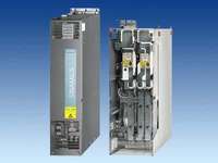
SINAMICS G130 - это преобразователь AC/AC, который может быть соединён с другими компонентами системы и установлен в требуемый шкаф управления или непосредственно на машину.
Преобразователи SINAMICS G130 доступны со следующими напряжениями питания и мощностями:
|
Напряжение питания
|
Мощность
|
|
от 380 В до 480 В
|
от 315 кВт до 560 кВт
|
|
от 660 В до 690 В
|
от 315 кВт до 800 кВт
|
Предоставляется широкий спектр дополнительных компонентов для любых применений. Настройка и наладка значительно упрощены предопределёнными интерфейсами.
Точность векторного бездатчикого управления достаточна для большинства применений, делая установку дополнительных энкодеров определения скорости вращения зачастую избыточным.
При этом SINAMICS G130 имеет опцию для подключения энкодера, если это необходимо по производственным причинам.
Взаимодействие между блоком управления, силовым блоком и прочими активными элементами SINAMICS происходит через DRIVE-CliQ - внутренний интерфейс привода. Для соединения по DRIVE-CLiQ поставляются готовые кабели различной длины, обеспечивая быструю сборку системы.
В стандартный комплект также входят PROFIBUS интерфейс и клеммный блок с аналоговыми и цифровыми входами/выходами для подключения сигналов заказчика.
Область применения
Variable-speed drives are advantageous for all applications that involve moving, conveying, pumping or compressing solids, liquids or gases.
This means the following applications, in particular:
• Pumps and fans
• Compressors
• Extruders and mixers
• Mills
Тех. данные
Особенности
- Particularly quiet and compact converters due to the use of state-of-the-art IGBT power semiconductors and an innovative cooling concept
- Increase in plant availability since individual modules and power components can be replaced quickly and easily. The design of replaceable components is based on the principle that they must be quick and easy to change. In addition, the "SparesOnWeb" Internet tool makes it easy to view the spare parts that are available for the system components ordered.
- Can be easily integrated into automation solutions due to a standard communications interface and various analog and digital interfaces.
- Easy commissioning and parameterization using interactive menus on the user-friendly AOP30 Advanced Operator Panel with graphical LCD and plain-text display, or from a PC using the STARTER commissioning tool (→ Tools and configuration)
- Preset software functions make it easier to tailor the converter to the individual plant
- All components, from individual parts to the ready-to-connect cabinet, undergo rigorous testing throughout the entire production process. This guarantees a high level of functional reliability during installation and commissioning, as well as in operation.
Дизайн
The SINAMICS G130 drive converter chassis unit provides machine builders and plant constructors with a modular drive system that can be tailored to specific applications.
SINAMICS G130 drive converter chassis units consist of two modular, stand-alone components:
• Power Module and
• Control Unit
They may be located separately from one another or combined in a single unit. The Power Module contains a slot for the Control Unit.
The Power Modules are supplied with a DRIVE-CLiQ cable for communication and a cable for the 24 V supply to the Control Unit. These cables are pre-assembled for installing the Control Unit in the Power Module. If the two units are in a separate location, the cables must be ordered in the appropriate lengths.
The user-friendly AOP30 Advanced Operator Panel and the BOP20 Basic Operator Panel can be used for commissioning and local operation.
Predefined interfaces, via terminal block or PROFIBUS, make the commissioning and control of the drive much easier. The interfaces of the CU320 Control Unit can be supplemented with additional modules, such as the plug-in TB30 Terminal Board or the TM31 Terminal Module.
If further customer interfaces are needed to communicate with the drive, an external 24 V supply must be provided.
The two following figures are helpful when it comes to assembling the required converter components correctly.
The first figure shows the structure and the individual components of a SINAMICS G130 drive. The second figure is a flowchart containing the decision and selection criteria required for the individual components.

Функции
Communication with higher-level control and customer’s terminal block
A communications interface on the CU320 Control Unit, the TM31 Terminal Module, the TB30 Terminal Board and expansions for supporting PROFINET and CANopen are provided as standard for use as the customer interface.
You can use this customer’s terminal block to connect the system to the higher-level controller using analog and digital signals, or to connect additional units.
To simplify configuration and commissioning of the drive, the TM31 Terminal Module can be preset to a variety of factory settings.
For more detailed information, please refer to the Engineering Manual SINAMICS Low Voltage. The engineering manual is stored as a PDF file on the CD-ROM included with the catalog.
Open-loop and closed-loop control functions
The converter control contains a high-quality Vector Control with speed and current controls as well as motor and converter protection.
Software and protection functions
The software functions available as standard are described below:
|
Software and protection functions
|
|
|
Setpoint input
|
The setpoint can be defined internally or externally, internally as fixed or motorized potentiometer or jog setpoints, externally via the communications interface or an analog input of the customer’s terminal block. The internal fixed setpoint and the motorized potentiometer setpoint can be switched over or adjusted using control commands via all interfaces.
|
|
Motor identification
|
The automatic motor identification permits fast and simple commissioning and optimization of the drive control.
|
|
Ramp-function generator
|
A user-friendly ramp-function generator with separately adjustable ramp-up and ramp-down times, together with adjustable rounding times in the lower and upper speed ranges, improves the control response and therefore prevents mechanical overloading of the drive train. The ramp-down ramps can be parameterized separately for emergency stop.
|
|
Vdc max controller
|
The Vdc max controller automatically prevents overvoltages in the DC link if the set ramp-down ramp is too short, for example. This can also extend the set ramp-down time.
|
|
Kinetic buffering (KIP)
|
Line voltage failures are bridged to the extent permitted by the kinetic energy of the drive train. The speed drops depending on the moment of inertia and load torque. The current speed setpoint is resumed when the line voltage returns.
|
|
Automatic restart 1)
|
The automatic restart switches the drive on again when the power is restored after a power failure, and ramps up to the current speed setpoint.
|
|
Flying restart 1)
|
The flying restart permits bumpless connection of the converter to a rotating motor.
|
|
Technology controller
|
The "Technology controller" function module allows simple control functions to be implemented, e.g. level control or volumetric flow control. The technology controller is designed as a PID controller, whereby the dfferentiator can be switched to the control deviation channel or the actual value channel (factory setting). The P, I, and D components can be set separately.
|
|
Free function blocks
|
Drive Control Chart (DCC) is an additional tool for the easy configuration of process-oriented functions for the SINAMICS G130. The block library contains a large selection of control, arithmetic and logic blocks as well as extensive open-loop and closed-loop control functions. The user-friendly DCC editor enables easy graphical configuration and a clear representation of control loop structures as well as a high degree of reusability of existing diagrams. DCC is an add-on to the STARTER commissioning tool (Tools and configuration).
|
|
Drive Control Chart (DCC)
|
Drive Control Chart (DCC) is an additional tool for the easy configuration of process-oriented functions for the SINAMICS G130. The block library contains a large selection of control, arithmetic and logic blocks as well as extensive open-loop and closed-loop control functions. The user-friendly DCC editor enables easy graphical configuration and a clear representation of control loop structures as well as a high degree of reusability of existing diagrams. DCC is an add-on to the STARTER commissioning tool (# Tools and configuration).
|
|
I²t detection for motor protection
|
The motor temperature is calculated in a motor model stored in the converter software, taking into account the current speed and load. More exact sensing of the temperature, also taking into account the influence of the ambient temperature, is possible by means of direct temperature sensing using KTY84 sensors in the motor winding.
|
|
Evaluation of motor temperature
|
Motor protection by evaluating a KTY84 or PTC temperature sensor. When a KTY84 sensor is connected, the limit values can be set for alarm or shutdown. When connecting a PTC thermistor, the reaction following triggering of the PTC thermistor (alarm or shutdown) can be defined.
|
|
Motor blocking protection
|
A blocked motor is recognized and protected against thermal overloading by shutting down.
|
1) Factory setting: not activated (can be parameterized)
|
Safety Integrated
|
|
Safe Torque Off (STO)
|
Description of functions
This function prevents the drive from restarting unexpectedly in accordance with EN 60204-1, Section 5.4. Safe Torque Off disables the drive pulses and disconnects the power supply to the motor (corresponds to Stop Category 0 of EN 60204-1). The drive is reliably torque-free. This state is monitored internally in the drive.
Application, customer benefits
STO has the immediate effect that the drive cannot supply any more torque-generating energy. STO can be used wherever the drive will reach a standstill in a sufficiently short time based on the load or when coasting down of the drive will not have any relevance for safety.

|
|
Safe Stop 1 (SS1)
|
Description of functions
The Safe Stop 1 function can safely stop the drive in accordance with EN 60204-1, Stop Category 1. When the SS1 function is selected, the drive brakes along a quick stop ramp (OFF3) and automatically activates the Safe Torque Off when the parameterized safety delay timer runs down.
Application, customer benefits
When the stop function of the drive is activated and it does not come to a halt quickly enough due to the load inertia, it can be actively braked by the converter. This integrated quick braking function eliminates the need for costly mechanical brakes that are subject to wear.

The Safety Integrated functions STO and SS1 of SINAMICS G130 are certified by independent institutes. The appropriate external test certificates and manufacturer declarations are available from the Siemens representatives, as well as at http://support.automation.siemens.com/WW/view/en/23158850
|
|
Power unit protection
|
|
Ground fault monitoring at output side
|
A ground fault on the output side is recognized by aggregate current monitoring, and results in shutdown in grounded networks.
|
|
Electronic short-circuit protection
on output side
|
A short-circuit (e.g. on the converter output terminals, in the motor cable or in the motor’s terminal box) is detected on the output side and the converter switches off with a fault.
|
|
Thermal overload protection
|
A warning message is issued first when the overtemperature threshold responds. If the temperature rises further, either a shutdown is carried out or an automatic influencing of the pulse frequency or output current takes place so that a reduction in the thermal load is achieved. After elimination of the cause of the fault (e.g., improvement in the ventilation), the original operating values are automatically resumed.
|
Технические данные
|
Electrical data
|
|
Line voltages and power ranges
|
- 380 ... 480 V 3 AC, ±10 % (-15 % < 1 min) 110 ... 560 kW
- 500 ... 600 V 3 AC, ±10 % (-15 % < 1 min) 110 ... 560 kW
- 660 ... 690 V 3 AC, ±10 % (-15 % < 1 min) 75 ... 800 kW
|
|
Supply systems
|
TN/TT line supplies or isolated supplies (IT line supplies)
|
|
Line frequency
|
47 ... 63 Hz
|
|
Output frequency
|
0 ... 300 Hz
|
|
Power factor
|
|
|
|
> 0.98
|
|
|
0.93 ... 0.96
|
|
Converter efficiency
|
> 98 %
|
|
Control method
|
Vector Control with and without sensor or V/f control
|
|
Fixed speeds
|
15 fixed speeds plus 1 minimum speed, parameterizable (in the default setting, 3 fixed setpoints plus 1 minimum speed are selectable using terminal block/PROFIBUS)
|
|
Skipped speed ranges
|
4, parameterizable
|
|
Setpoint resolution
|
0.001 rpm digital
12 bit analog
|
|
Braking operation
|
By means of additional Braking Modules and braking resistors
|
|
Mechanical data
|
|
Degree of protection
|
IP00 or IP20 dependent on type
|
|
Protection classΙ
|
in accordance with EN 61800-5-1
|
|
Cooling method
|
Forced air cooling AF in accordance with EN 60146
|
|
Sound pressure level LpA (1 m)
|
≤ 73 dB at 50 Hz line frequency
|
|
Shock protection
|
BGV A3
|
|
Compliance with standards
|
|
Standards
|
EN 61800-5-1
EN 60146‑1, EN 61800‑2, EN 61800‑3, EN 60204‑1, EN 60529 1)
|
|
CE marking
|
In accordance with EMC directive No. 2004/108/EC and low-voltage directive No. 2006/95/EC
|
|
EMC conformance
|
The SINAMICS G130 converter systems are not designed for connection to the public power network ("First environment"). EMC conformance is compliant with the EMC product standard for variable-speed drives EN 61800-3, "Second environment" (industrial networks). The equipment can cause electromagnetic interference when it is connected to the public network. If supplementary measures are taken (e.g. → line filter), it can also be operated in the "First environment".
|
|
Approvals
|
cULus (File No. E192450)
|
| |
|
| |
Storage
|
Transport
|
Operation
|
|
Ambient conditions
|
|
Ambient temperature
|
-25 ... +55 °C
|
‑25 ... +70 °C
from -40 °C for 24 hours
|
0 ... +40 °C
up to +50 °C see derating data
|
|
Relative humidity 1)
(non-condensing)
|
5 ... 95 %
|
5 ... 95 %
at 40 °C
|
5 ... 95 %
|
| |
Corr. to 1K4 to EN 60721-3-1
|
Corr. to 2K3 to EN 60721-3-2
|
Corr. to 3K3 to EN 60721-3-3
|
|
Environmental class/harmful chemical
substances 1)
|
Class 1C2 to EN 60721-3-1
|
Class 2C2 to EN 60721-3-2
|
Class 3C2 to EN 60721-3-3
|
|
Organic/biological influences 1)
|
Class 1B1 to EN 60721-3-1
|
Class 2B1 to EN 60721-3-2
|
Class 3B1 to EN 60721-3-3
|
|
Installation altitude
|
up to 2000 m above sea level without derating, > 2000 m see derating data
|
|
Strain resistance
|
|
Vibratory load 1)
|
|
|
1.5 mm at 5 ... 9 Hz
|
3.1 mm at 5 ... 9 Hz
|
0.075 mm at 10 ... 58 Hz
|
|
|
5 m/s2 at > 9 ... 200 Hz
|
10 m/s2 at > 9 ... 200 Hz
|
10 m/s2 at > 58 ... 200 Hz
|
| |
Corr. to 1M2 to EN 60721-3-1
|
Corr. to 2M2 to EN 60721-3-2
|
–
|
|
Shock load 1)
|
|
|
40 m/s2 at 22 ms
|
100 m/s2 at 11 ms
|
100 m/s2 at 11 ms
|
| |
Corr. to 1M2 to EN 60721-3-1
|
Corr. to 2M2 to EN 60721-3-2
|
Corr. to 3M4 to EN 60721-3-3
|
Deviations from the defined classes are identified by underlining.
1) The EN standards specified are the European editions of the international IEC standards with the same designations.
Derating data
Compensation of current derating as a function of installation altitude/ambient temperature
If the SINAMICS G130 chassis units are operated at an installation altitude > 2000 m above sea level, factors relating to a reduction of the maximum permissible output current (derating) must be taken into account. These are specified in the tables below. It must be ensured that the air flow corresponds to the rate specified in the technical specification tables. The specified values already include a permitted correction between installation altitude and ambient temperature (incoming air temperature at the inlet to the unit).
|
Installation altitude above sea level
m
|
Current derating
at an ambient temperature of
|
|
|
20 °C
|
25 °C
|
30 °C
|
35 °C
|
40 °C
|
45 °C
|
50 °C
|
|
0-2000
|
100 %
|
100 %
|
100 %
|
100 %
|
100 %
|
95.0 %
|
87.0 %
|
|
2001-2500
|
100 %
|
100 %
|
100 %
|
100 %
|
96.3 %
|
91.4 %
|
83.7 %
|
|
2501-3000
|
100 %
|
100 %
|
100 %
|
96.2 %
|
92.5 %
|
87.9 %
|
80.5 %
|
|
3001-3500
|
100 %
|
100 %
|
96.7 %
|
92.3 %
|
88.8 %
|
84.3 %
|
77.3 %
|
|
3501-4000
|
100 %
|
97.8 %
|
92.7 %
|
88.4 %
|
85.0 %
|
80.8 %
|
74.0 %
|
Current derating as a function of the ambient temperature (incoming air temperature) and installation altitude
Voltage derating as a function of the installation altitude
In addition to current derating, voltage derating must be considered in accordance with the following table with installation altitudes > 2000 m above sea level.
|
Installation altitude above sea level
|
Voltage derating
for a rated input voltage of
|
|
m
|
380 V
|
400 V
|
420 V
|
440 V
|
460 V
|
480 V
|
500 V
|
525 V
|
550 V
|
575 V
|
600 V
|
660 V
|
690 V
|
|
0-2000
|
100 %
|
100 %
|
100 %
|
100 %
|
100 %
|
100 %
|
100 %
|
100 %
|
100 %
|
100 %
|
100 %
|
100 %
|
100 %
|
|
2001-2250
|
100 %
|
100 %
|
100 %
|
100 %
|
100 %
|
96 %
|
100 %
|
100 %
|
100 %
|
100 %
|
100 %
|
100 %
|
96 %
|
|
2251-2500
|
100 %
|
100 %
|
100 %
|
100 %
|
98 %
|
94 %
|
100 %
|
100 %
|
100 %
|
100 %
|
100 %
|
98 %
|
94 %
|
|
2501-2750
|
100 %
|
100 %
|
100 %
|
98 %
|
94 %
|
90 %
|
100 %
|
100 %
|
100 %
|
100 %
|
100 %
|
95 %
|
90 %
|
|
2751-3000
|
100 %
|
100 %
|
100 %
|
95 %
|
91 %
|
88 %
|
100 %
|
100 %
|
100 %
|
100 %
|
100 %
|
92 %
|
88 %
|
|
3001-3250
|
100 %
|
100 %
|
97 %
|
93 %
|
89 %
|
85 %
|
100 %
|
100 %
|
100 %
|
100 %
|
98 %
|
89 %
|
85 %
|
|
3251-3500
|
100 %
|
98 %
|
93 %
|
89 %
|
85 %
|
82 %
|
100 %
|
100 %
|
100 %
|
98 %
|
95 %
|
85 %
|
82 %
|
|
3501-3750
|
100 %
|
95 %
|
91 %
|
87 %
|
83 %
|
79 %
|
100 %
|
100 %
|
98 %
|
95 %
|
91 %
|
–
|
–
|
|
3751-4000
|
96 %
|
92 %
|
87 %
|
83 %
|
80 %
|
76 %
|
100 %
|
100 %
|
95 %
|
91 %
|
87 %
|
–
|
–
|
Voltage derating depending on installation altitude
Current derating depending on pulse frequency
To reduce motor noise or to increase output frequency, the pulse frequency can be increased relative to the factory setting. When the pulse frequency is increased, the derating factor of the output current must be taken into account. This derating factor must be applied to the currents specified in the technical specifications.
|
Order No.
6SL3310-…
|
Output
[kW]
|
Output current
at 2 kHz [A]
|
Derating factor
at 4 kHz
|
|
380 ... 480 V 3 AC
|
|
1GE32-1AA0
|
110
|
210
|
82 %
|
|
1GE32-6AA0
|
132
|
260
|
83 %
|
|
1GE33-1AA0
|
160
|
310
|
88 %
|
|
1GE33-8AA0
|
200
|
380
|
87 %
|
|
1GE35-0AA0
|
250
|
490
|
78 %
|
Deratingfaktor des Ausgangsstromes in Abhängigkeit der Pulsfrequenz bei Geräten mit 2 kHz Nennpulsfrequenz
|
Order No.
6SL3310-…
|
Output
[kW]
|
Output current
at 1.25 kHz [A]
|
Derating factor
at 2.5 kHz
|
|
380 ... 480 V 3 AC
|
|
1GE36-1AA0
|
315
|
605
|
72 %
|
|
1GE37-5AA0
|
400
|
745
|
72 %
|
|
1GE38-4AA0
|
450
|
840
|
79 %
|
|
1GE41-0AA0
|
560
|
985
|
87 %
|
|
500 ... 600 V 3 AC
|
|
1GF31-8AA0
|
110
|
175
|
87 %
|
|
1GF32-2AA0
|
132
|
215
|
87 %
|
|
1GF32-6AA0
|
160
|
260
|
88 %
|
|
1GF33-3AA0
|
200
|
330
|
82 %
|
|
1GF34-1AA0
|
250
|
410
|
82 %
|
|
1GF34-7AA0
|
315
|
465
|
87 %
|
|
1GF35-8AA0
|
400
|
575
|
85 %
|
|
1GF37-4AA0
|
500
|
735
|
79 %
|
|
1GF38-1AA0
|
560
|
810
|
72 %
|
|
660 ... 690 V 3 AC
|
|
1GH28-5AA0
|
75
|
85
|
89 %
|
|
1GH31-0AA0
|
90
|
100
|
88 %
|
|
1GH31-2AA0
|
110
|
120
|
88 %
|
|
1GH31-5AA0
|
132
|
150
|
84 %
|
|
1GH31-8AA0
|
160
|
175
|
87 %
|
|
1GH32-2AA0
|
200
|
215
|
87 %
|
|
1GH32-6AA0
|
250
|
260
|
88 %
|
|
1GH33-3AA0
|
315
|
330
|
82 %
|
|
1GH34-1AA0
|
400
|
410
|
82 %
|
|
1GH34-7AA0
|
450
|
465
|
87 %
|
|
1GH35-8AA0
|
560
|
575
|
85 %
|
|
1GH37-4AA0
|
710
|
735
|
79 %
|
|
1GH38-1AA0
|
800
|
810
|
72 %
|
Derating factor of the output current depending on the pulse frequency for units with a rated pulse frequency of 1.25 kHz
Overload capacity
SINAMICS G130 drive converter chassis units are equipped with an overload reserve to deal with breakaway torques, for example. If larger surge loads occur, this must be taken into account when configuring. In drives with overload requirements, the appropriate base load current must therefore be used as a basis for the required load.
The criterion for overload is that the drive is operated with its base load current before and after the overload occurs, and a load duration of 300 s is assumed here.
The base load current IL for a low overload is based on a duty cycle of 110 % for 60 s or 150 % for 10 s.
The base load current IH for a high overload is based on a duty cycle of 150 % for 60 s or 160 % for 10 s.

Low overload

High overload
EMC guidelines
The electromagnetic compatibility describes - in accordance with the definition of the EMC directive - the "capability of a device to work satisfactorily in the electromagnetic environment without itself causing electromagnetic interferences which are unacceptable for other devices present in this environment". To guarantee that the appropriate EMC directives are observed, the devices must demonstrate a sufficiently high noise immunity, and also the emitted interference must be limited to acceptable values.
The EMC requirements for "Variable-speed drive systems" are described in the product standard EN 61800-3. A variablespeed drive system (or power drive system, PDS) consists of the drive converter and the electric motor including cables. The driven machine is not part of the drive system. EN 61800-3 defines different limits depending on the location of the drive system, referred to as the first and second environment.
The first environment comprises living accomodation or locations where the drive system is directly connected to the public low-voltage network without an intermediate transformer.
The second environment is understood to be locations outside living areas. These are basically industrial areas which are powered from the medium-voltage network via their own transformers.
Four different categories are defined in EN 61800-3 depending on the location and the power of the drive:
Category C1: Drive systems for rated voltages < 1000 V for unlimited use in the first environment.
Category C2: Stationary drive systems for rated voltages < 1000 V for use in the second environment. Use in the first environment is possible if the drive system is installed and used by qualified personnel. The warning and installation information supplied by the manufacturer must be observed.
Category C3: Drive systems for rated voltages < 1000 V for exclusive use in the second environment.
Category C4: Drive systems for rated voltages % 1000 V or for rated currents % 400 A for use in complex systems in the second environment.
The following diagram shows the assignment of the four categories to the first and second environments:

SINAMICS G130 drive converter chassis units are almost exclusively used in the second environment (categories C3 and C4).
To limit the emitted interference, the SINAMICS G130 drive converter chassis units are equipped as standard with an RFI suppression filter in accordance with the limits specified in Category C3. This means that they meet the requirements for industrial use. Line filters are available for use in the first environment (Category C2).
SINAMICS G130 drive converter chassis units fulfill the requirements for noise immunity defined in EN 61800-3 for the second environment and consequently also the lower noise immunity values in the first environment.
The warning and installation information (part of the device documentation) must be observed.
Дальнейшая информация
Documentation
The device documentation consists of detailed operating instructions with the following sections:
Description
- Installation instructions
- Commissioning guide
- Function description
- Maintenance instructions
- Spare parts list
as well as equipment-specific dimensional drawings, arrangement diagrams, circuit and terminal diagrams.
The documentation is supplied as standard with the CU Kit on CD-ROM. The documentation is available in English, French, German, Italian and Spanish.