Обзор
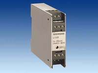 Область примененияThe U 309 adaptor module allows the U 307 digital motorized potentiometer to be operated also in the automatic mode with a reference setpoint of 4 to 20 mA (impressed current with live zero). Circuit description The circuit diagram is shown in the figure. A voltage of exactly 2.50 V is obtained via a voltage divider (R4-R7) from the +10.00 V reference voltage available at terminal 17 of the motorized potentiometer. This voltage is applied to input IN- of the motorized potentiometer (terminal 20) and compensates the 4 mA live zero current. A load resistance of exactly 634 W (R1 + R2 + R3) is inserted between terminals 21 and 23 of the motorized potentiometer; the 4 to 20 mA signal source is also connected at that point. The total signal excursion of 16 mA results in a voltage drop of exactly +10.00 V at motorized potentiometer input IN+. The input impedance of IN+ of 44 kW was taken into account for the design rating of the resistors. Заказные данные
Тех. данные
|


тел./факс: 8 (495) 229-56-79