Обзор
  Дополнительную информацию вы можете получить загрузив
файл в формате PDF (765013 байт).
Дополнительную информацию вы можете получить загрузив
файл в формате PDF (765013 байт).
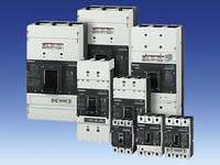
Обзор3VL molded case circuit breakers according to UL 489/IEC 60947-2 up to 1600 AОбласть примененияThe different versions of SENTRON 3VL UL circuit breakers are suitable for the following applications:
The SENTRON 3VL UL circuit breakers are available in the following versions: 1. For system protection (in 3-pole Versions) 2. For starter combinations (in 3-pole version) 3. As non-automatic air circuit breakers (in 3-pole Versions) Standards and specificationsSENTRON 3VL UL circuit breakers comply with: UL 489, Please contact Siemens for details of other standards. Operating conditionsThe SENTRON 3VL UL circuit breakers are designed for operation in enclosed areas. Тех. данные
Особенности
Дополнительную информацию вы можете получить загрузив
файл в формате PDF (154545 байт).
Дизайн
All circuit breakers are supplied with integrated electronic trip units. The SENTRON VL150X UL (CG frame) to VL1600 UL (PG frame) circuit breakers are available with different connection versions (see "Connections, Basic Equipment and Options"). Auxiliary switches/alarm switches or auxiliary trip units can be easily adapted by the customer, or they are also available ready installed if required. The switching capacity is shown on the front of every circuit breaker.
Standards and specificationsSENTRON 3VL UL circuit breakers comply with: UL 489, Please contact Siemens for details of other standards. The SENTRON 3VL UL circuit breakers comply in addition with requirements for "disconnector units with features for stopping and switching off in an emergency" (EMERGENCY-STOP switches) in conjunction with lockable rotary operating mechanisms (red-yellow) and terminal covers. Please contact Siemens for details of other standards. ConnectionThe following connection types are available for the SENTRON 3VL and approved according to UL 489:
The incoming and outgoing terminals for the circuit breaker can be freely selected. The electrical specifications remain the same. Bare conductors at the top connections must be insulated in the arc quenching space that is necessary above the arc chutes. For the SENTRON VL150X UL (CG frame) to VL1600 UL (PG frame) circuit breakers, the connections for the internal accessories (auxiliary trip units, auxiliary switches and alarm switches) are supplied with terminal screws. The auxiliary trip units (shunt trip units and undervoltage trip units), auxiliary switches and alarm switches for all SENTRON 3VL circuit breakers can be connected easily and directly. The motorized operating mechanisms with stored-energy features are always equipped with terminals. The leading auxiliary switches for the rotary operating mechanisms are always supplied with connecting cables. SENTRON VL150X UL (CG frame) to VL1600 UL (PG frame) circuit breakersThe main components of the SENTRON 3VL UL circuit breakers are the three conducting paths with the incoming and outgoing terminals. The fixed and moving contacts are designed in such a way that the contacts are magnetically repelled if there is a short-circuit. In conjunction with the arcing chambers, a dynamic impedance is created that causes current limiting due to a reduction in the damaging effects of I2t and Ip-energy that arises during short-circuits. The circuit breaker is trip-free. To the right and left of the operating mechanism, the double-insulated accessory compartments are situated for the auxiliary trip units and auxiliary switches. The trip units for the SENTRON VL150X UL (CG frame) to VL1600 UL (PG frame) have the following features:
As is the case for all versions of the SENTRON 3VL UL circuit breakers with electronic trip units, the current transformers are in the same enclosure as the trip units. They send a signal which is proportional to the load current to the electronic overcurrent tripping unit. All SENTRON 3VL UL circuit breakers with electronic trip units measure the actual r.m.s. current. This type of measurement is the most accurate method. Currents in today's electrical distribution systems with many harmonics are evaluated reliably. Overcurrent trip unit systemsThe trip unit is delivered ex-works with the switch unit. The infeed and outgoing terminals for the circuit breaker can only be freely selected for complete switches. 1. Overcurrent trip units for the SENTRON VL150X UL (CG frame) to VL1600 UL (PG frame) circuit breakers, thermal-magnetic The overcurrent and short-circuit releases work with bimetallic and magnetic trip units. They are available with fixed set overcurrent trip units and settable short-circuit trips units. The circuit breakers for starter combination applications are usually combined with a motor contactor and a suitable overload relay. The non-automatic air circuit breakers have an integrated short-circuit self-protection system eliminating the need for back-up fuses. Non-automatic air circuit breakers have no overload protection. 2. Overcurrent trips of the SENTRON circuit breaker VL150 UL (DG -Frame) to VL1600 UL (PG-Frame) are electronic, ETU The electronic overcurrent trip unit system consists of:
The left accessory compartment is required for the trip magnets for the SENTRON VL150 UL (DG frame) and VL250 (FG frame). The protection functions of the solid-state overcurrent trip units are maintained without additional auxiliary voltage. The electronic trip units are supplied with energy through circuit breaker-internal current transformers. The solid-state overcurrent trip unit has to be activated for parameterizing. This requires a load current of at least 20 % of the respective rated current In of the circuit breaker. If this load current is not available, the necessary auxiliary power can be fed in through a 3VL9 000-8AP01 battery power supply or through the 3VL9 000-8AK01 function tester. For communication-capable circuit breakers the trip unit is supplied with energy through COM10. At the output of the electronic overcurrent trip unit module there is a tripping solenoid which trips in the case of overload or short-circuit.
SENTRON VL150 UL (DG -Frame) to VL1600 UL (PG-Frame) electronic trip units – Overview of functionsInternal accessories (auxiliary switches, undervoltage trip units, shunt trip units)The SENTRON 3VL UL circuit breakers can be supplied with all the internal accessories (e.g. auxiliary switches, undervoltage trip units or shunt trip units). The available versions can be found in the tables with the Order No. supplements. Fixed-mounted, plug-in or withdrawable versionThe fixed-mounted circuit breaker is the basic version. This can be converted very easily into a plug-in or withdrawable version with the aid of the appropriate installation kit. This kit contains blade contacts, a locking pin and terminal covers for the plug-in version. The assembly kit for the withdrawable version also contains side covers and a moving mechanism. Even with the masking frame mounted, it is still possible to move using the handle with the door closed. Operating mechanismsThe basic versions of the SENTRON 3VL UL circuit breakers are equipped with a toggle lever as an operating mechanism which is also used as a switch position indicator. In addition to "ON" and "OFF", "Tripped" is also indicated. The toggle lever assumes the "tripped" position when the internal tripping mechanism is activated by an overcurrent tripping, e.g. an overload or short-circuit. The activation of an undervoltage trip unit or shunt trip unit also causes the toggle lever to assume the "tripped" position. The toggle lever must be put into the "OFF/RESET" position before the circuit breakers can be reclosed. It will then be possible to reset the internal tripping mechanism and reclose the main contacts on the circuit breaker (see figure). A toggle lever extension is supplied with the SENTRON VL 1200 UL (NG-Frame) and VL1600 UL (PG-Frame) circuit breakers. This accessory must be ordered separately for SENTRON VL400 UL (JG-Frame) to VL800 UL (MG-Frame), if required. Front-operated rotary operating mechanisms These operating mechanisms have been designed for direct mounting to the circuit breaker and change the toggle lever movement from a linear to a rotary motion. A leading voltage can be applied to the undervoltage trip unit of a circuit breaker with leading auxiliary switches which makes the circuit breaker ready-to-close. Door-coupling rotary operating mechanisms (complete operating mechanisms) Door-coupling rotary operating mechanisms and removable covers are available for circuit breakers which are installed into control cabinets and distribution boards. These are supplied as complete sets, including an articulated-shaft mechanism. With regard to the switching status indication and the "RESET" position, the same applies to the rotary operating mechanisms as to the toggle lever. The position of the operator lever (knob) indicates the status. This means that all SENTRON 3VL UL circuit breakers which have these rotary operating mechanisms as well as the corresponding terminal covers can be used as main control switches. 
Toggle lever operating mechanism positions 
Rotary operating mechanism secured with a padlock Motorized operating mechanismsThe SENTRON VL150X UL (CG frame) to VL1600 UL (PG frame) circuit breakers can be equipped with motorized operating mechanism for remote opening and closing during operation. These motorized operating mechanisms for SENTRON VL150X UL (CG frame) to VL800 UL (MG frame) circuit breakers have a spring energy store (for synchronization) with a maximum ON period of tE ≤ 100 ms. For SENTRON VL1200 UL (NG-Frame) and VL1600 UL (PG-Frame) circuit breakers there are motorized operating mechanisms without a spring energy store for remote-controlled ON and OFF switching. All motorized operating mechanisms are always supplied with a locking device for padlocks. Optional safety locks are also available for motorized operating mechanisms with spring energy store. These locking devices can be used to block the operating mechanism electrically and mechanically. All remote-controlled operating mechanisms are equipped with a manual operation option for maintenance purposes. The motorized operating mechanisms with spring energy store for VL150X UL (CG frame) to VL800 UL (MG frame) as well as the motorized operating mechanisms for VL1200 UL (NG frame) and VL1600 UL (PG frame) are each equipped inside with a signaling contact (NO) for the following functions:
Main circuit connections, basic equipment and options
X Available -- Not available 1) Multiple feed terminal. 2) Circular conductor terminal also available. Auxiliary switches and auxiliary trip unitsUndervoltage trip units, leading auxiliary switches If there is no voltage present, closing of the circuit breaker is not possible. If voltage is not applied to the trip units, operation of the circuit breaker will result in no-load switching. Frequent re-tripping should be avoided because of its adverse effect on the endurance of the circuit breaker. A leading voltage can be applied to the undervoltage trip unit of a circuit breaker with leading auxiliary switches which makes the circuit breaker ready-to-close. For SENTRON 3VL UL circuit breakers, the leading auxiliary switch can be supplied with the front rotary operating mechanism or complete operating mechanism. For more detailed information please refer to the selection and ordering tables for accessories. Shunt trip units The shunt trip unit is used for remote tripping of the circuit breaker. The coil of the shunt trip unit is designed for short-time operation only. A coil trip is implemented internally. It is not permissible to apply a continuous trip command to a shunt trip unit to prevent closing when the circuit breaker is tripped. A central tap is provided as standard for checking the conductivity of the coil. 
Possible complement for the insulated accessory subsections in the SENTRON 3VL UL circuit breakers Before ordering, use the table above to check whether the required combination of shunt trip units, undervoltage trip units and auxiliary/alarm switches is feasible. Auxiliary switches Auxiliary switches (HS) are used for indication and control. The contacts of the auxiliary switches close and open together with the main contacts. Alarm switches The alarm switches (AS) are active when the circuit breaker has been tripped due to an overcurrent e.g. overload or short-circuit. However, they are also activated if the circuit breaker has been tripped by a shunt trip unit or undervoltage trip unit. Installation of internal accessories The insulated accessory subsections for installing accessories (auxiliary trip units and auxiliary switches/alarm switches) have the designations X1, X2 and X4. The equipping of the circuit breaker with internal accessories and the configuration possibilities for circuit breakers with auxiliary trip units and auxiliary switches/alarm switches depend on the mounting position and size of the circuit breaker (see the illustration "Possible Complements for the Insulated Accessory Subsections of the 3VL UL Circuit Breakers"). PLC control The auxiliary and alarm switches can be used to send signals to PLCs. These switch blocks are part of the Siemens 3SB3 range. Leading auxiliary switches The leading auxiliary switches OFF to ON or ON to OFF are available as a retrofit set for rotary operating mechanisms. ФункцииCurrent limiting1)The SENTRON 3VL UL circuit breakers utilize the design principle of magnetic repulsion of the contacts. The contacts open before the anticipated peak value of the short-circuit current is achieved. The current-limiting effects of the SENTRON 3VL UL circuit breakers provide effective protection for system components against the thermal and dynamic effects of the short-circuit current in the event of an electrical fault. 1) Current limiting according to IEC 60947-2. Ground-fault protectionGround-fault release "G" sense fault currents that flow to round and that can cause fire in the plant. Several circuit breakers connected in series can provide graduated discrimination by means of the adjustable delay time. The following measurement methods can be used to detect neutral conductor and ground-fault currents: Vectorial summation current formation (measurement method 1) Ground-fault detection in symmetrically loaded systems The three phase currents are evaluated with the help of the vectorial summation current formation. 
Ground-fault detection in asymmetrically loaded systems The neutral conductor current is measured directly. For the 3-pole circuit breakers, this measurement is only evaluated for ground-fault protection. The electronic trip unit determines the ground-fault current for the three phase currents and neutral conductor current by means of vectorial summation current formation. 
3-pole circuit breaker, current transformer in the neutral conductor Direct detection of the ground-fault current through a current transformer in the grounded neutral point of the transformer (measurement method 2) The current transformer is installed directly in the grounded neutral point of the transformer. 
3-pole circuit breakers, current transformers in the grounded neutral point of the transformer. Transformer protection The SENTRON 3VL UL circuit-breakers protect energy distribution systems against overload and short-circuit on the low-voltage side of the infeed transformer. The resulting requirements with respect to current-based and/or time-based discrimination are reliably fulfilled by the SENTRON 3VL UL circuit-breakers for system protection (equipped with thermal-magnetic (TM) or electronic overcurrent trip units (ETU or LCD ETU). Thermal-magnetic overcurrent trip unit
1) Size dependent, see "Selection and Ordering Data". Electronic trip units ETU
1) Size dependent, see "Selection and Ordering Data". Solid-state overcurrent trip unit LCD ETU
1) Size dependent, see "Selection and Ordering Data". КонфигурацияCommunicationTwo alternatives are available for communication. An LCD ETU (model 576) is required in addition for the more extensive communication with COM10. It is possible to switch on and off using an optional motorized operating mechanism. Transmittable data
✓ Available -- Not available Functions of the communication components
✓ Required ❑ Not necessary for this function, optionally combinable -- Function not available Switching of DC currentsThe VL150X UL (CG frame) to VL1600 UL (PG frame) circuit breakers (for system protection with TM, for starter combinations, non-automatic air circuit breakers) can also be used for DC switching and protection applications. The VL150X UL (CG frame) to VL1600 UL (PG frame) circuit breakers with electronic trip units (ETU) are not suitable for DC applications. However, the maximum permitted DC voltage for each conducting path needs to be taken into account for DC switching applications. Voltages above 250 V at VL150 UL (DG frame) to VL1600 UL (PG frame) require a series connection with 2 or 3 conducting paths. As the current has to flow through all of the conducting paths, the following connections are recommended in order to satisfy the thermal tripping characteristics. With DC applications, the response values of the instantaneous short-circuit releases ("I" releases ) are increased by 30 to 40 %. For 3-pole circuit breakers
Дополнительную информацию вы можете получить загрузив
файл в формате PDF (305779 байт).
Технические данныеХарактеристикаCharacteristic curves and certificatesGeneral: The indicated tripping values for the inverse-time delayed electronic trip units (thermal overload trip releases, "L" trip units) are mean values taken from the spread of all setting ranges from the cold state and under even load conditions on the conducting paths. The tripping characteristic curves of the instantaneous (electromagnetic) short-circuit releases ("I" trip units) are based on the phase rated current In. For thermomagnetic trip units (TM), the following applies: The characteristic curves apply to the cold state; at operating temperature, the tripping times of the thermal trip units are reduced to approximately 25 %. Under normal operating conditions, all three poles of the device must be loaded. The three main current paths must be connected in series in order to protect single-phase or DC loads. Tripping characteristic curves of the SENTRON VL150 UL (DG frame) to VL1600 UL (PG frame) circuit breakers for generator protection with solid-state overcurrent trip units. The tripping times of the inverse-time delayed overcurrent trip units apply to the non-preloaded (cold) state. In the operating/warm state (after application of a load at the rated current), the tripping times are reduced to approx. 33 %. After a tripping operation due to overcurrent, the tripping times are reduced in accordance with the dynamic tripping response, which means that a cooling time of a few minutes is required before the next motor start. Detailed time/current characteristic curves, current limiting characteristic curves, I2t curves and certificates can be ordered from "Technical Assistance" (e-mail: technical-assistance@siemens.com) or downloaded from the following Internet sites: or |
|||||||||||||||||||||||||||||||||||||||||||||||||||||||||||||||||||||||||||||||||||||||||||||||||||||||||||||||||||||||||||||||||||||||||||||||||||||||||||||||||||||||||||||||||||||||||||||||||||||||||||||||||||||||||||||||||||||||||||||||||||||||||||||||||||||||


тел./факс: 8 (495) 229-56-79